A first order tire and wheel vibration is usually the result of one
of the following five conditions:
| • | Excessive radial runout |
| • | Excessive lateral runout |
| • | Excessive radial force variation |
| • | Excessive lateral force variation |
These conditions must be eliminated one at a time in order to attain
a set of tires that are free from vibration causing elements. Substitute a
set of tires from another vehicle only as a last resort, and only after the
tires have been tested on a similar vehicle under the same conditions. Correcting
the existing tire and wheel assemblies is the most accurate and least time
consuming approach. This is due to vehicle-to-vehicle sensitivities and the
differences between the hubs of any two vehicles.
Methods of Measuring Tire/Wheel Assembly Runout
The tire and wheel assembly runout will directly affect the amount of
the imbalance and the radial force variation. Therefore, correct the runout
first before further diagnosis. The less runout, the less imbalance and radial
force variation. Radial and lateral runout can be corrected at the same time.
There are two methods for correcting the tire and wheel assembly runout:
| • | The on-vehicle method, with the tire and wheel assembly mounted
on the hub. The wheel bearing must be in good condition. |
| • | The off-vehicle method, with the tire and wheel assembly mounted
on a spin-type tire balancer. |
Perform the following initial on-vehicle inspections prior to the off-vehicle
runout checks:
- Inspect the tires for any uneven bead seatings. The distance
from the edge of the ring to the concentric rim locating ring should be equal
around the entire circumference.
- Properly mount the tires if the beads are not seated properly
in order to avoid excessive runout and imbalance.

The off-vehicle method is the easiest way of measuring the tire and
wheel runout. Properly mounting the dial indicator in the correct location
in relation to the tire (1) is easier. The dial indicator is less likely to
be subjected to water, snow, dirt, or other elements. After measuring the
correct runout off-vehicle, inspect the runout with the tire and wheel assembly
mounted on the vehicle. The runout measurement may vary greatly between these
two methods. If so, the runout is due to one of the following conditions:
| • | A mounting problem between the wheel and the vehicle |
Measuring Tire/Wheel Assembly Runout
If the vehicle has been sitting in one place for an extended period
of time, the tires may develop flat spots at the point where the tires were
resting on the ground. These flat spots will affect the runout readings. In
order to eliminate these flat spots, drive the vehicle long enough to warm
up the tires. The flat spots must be eliminated prior to taking any runout
measurements.
Measurement Procedure
- Raise and suitably support the vehicle. Refer to
Lifting and Jacking the Vehicle
in General
Information.
- Obtain an initial indication of how much runout exists:
| 2.1. | Spin the each tire and wheel assembly on the vehicle by hand (or
at a slow speed using the engine to run the drive wheels). |
| 2.2. | Visually inspect the amount of runout from the front or rear of
the tire. |
- Matchmark the location of each of the tire and wheel assemblies
in relation to the wheel studs and to their position on the vehicle (LF, LR,
RF, RR) for future reference.
- Remove the tire and wheel assemblies one at a time and mount on
a spin-type wheel balancer. Refer to
Wheel Removal
in Tires and Wheels.
Locate the tire and wheel assembly on the balancer with a cone through
the back side of the center pilot hole.

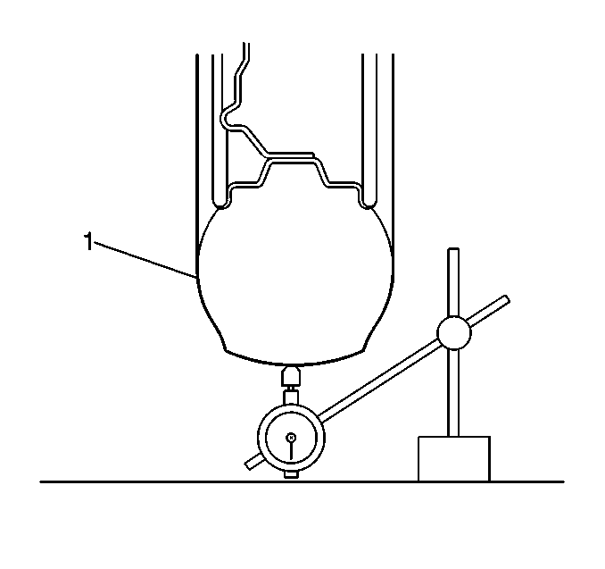
- Wrap the outer circumference
of tires that use an all-season or aggressive tread pattern with tape (1),
in order to accurately measure the radial runout.
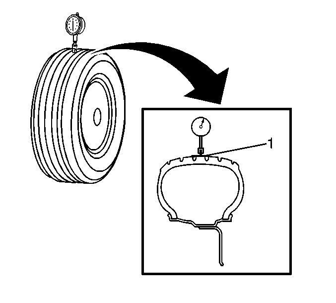
- Measure the tire and wheel assembly radial runout.
| 6.1. | Slowly rotate the tire and wheel assembly one complete revolution
and ZERO the dial indicator on the low spot. |
| 6.2. | Rotate the assembly one more complete revolution and note the
total amount of runout indicated. |
Maximum Radial Runout
| • | Measured off-vehicle: 1.27 mm (0.050 in) |
| • | Measured on-vehicle: 1.52 mm (0.060 in) |

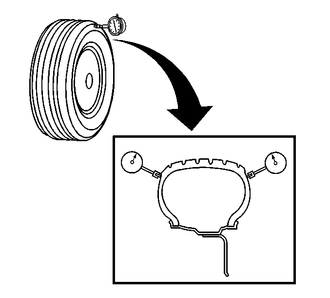
- Measure the tire and wheel
assembly lateral runout.
Lateral runout should be measured on a smooth area of the sidewall as
close to the tread as possible. Ignore any jumps or dips due to sidewall splices
and attain an average amount of runout.
| 7.1. | Slowly rotate the tire and wheel assembly one complete revolution
and ZERO the dial indicator on the low spot. |
| 7.2. | Rotate the assembly one more complete revolution and note the
total amount of runout indicated. |
Maximum Lateral Runout
| • | Measured off-vehicle: 1.27 mm (0.050 in) |
| • | Measured on-vehicle: 1.52 mm (0.060 in) |
- Make the necessary repairs to the tire and wheel assembly.
- Install the tire and wheel assembly to the vehicle. Refer to
Wheel Removal
in Tires and Wheels.
- Repeat the procedure until all the wheel runouts have been measured.
- Lower the vehicle.


