For 1990-2009 cars only
Removal Procedure
- Raise and support the vehicle. Refer to Lifting and Jacking the Vehicle in General Information.
- Remove the tire and wheel assembly. Refer to Wheel Removal in Tires and Wheels.
- Remove the stabilizer shaft link. Refer to .
- Remove the ball joint from the knuckle. Refer to Lower Control Arm Ball Joint Replacement .
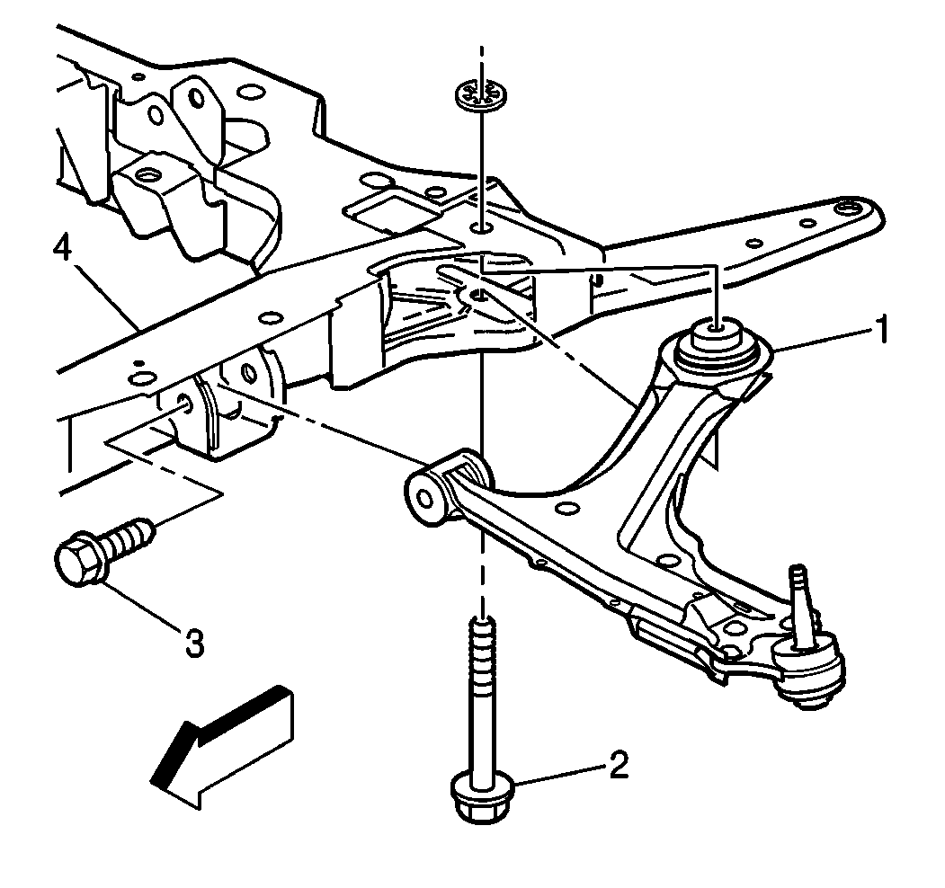
- Remove the bolt (2) attaching the control arm (1) to the crossmember (4).
- Remove the bolt (3) from the control arm (1).
- Remove the control arm (1) from the vehicle.

Installation Procedure
- Install the control arm (1) into position and install the bolt (2) attaching the control arm (1) to the crossmember (4).
- Install the bolt (3) to the control arm (1).
- Install the stabilizer shaft link. Refer to . Stabilizer Shaft Link Replacement
- Install the lower ball joint to the steering knuckle. Refer to Lower Control Arm Ball Joint Replacement .
- Slightly raise the vehicle.
- Remove the jack stands from under the crossmember.
- Install the tire and wheel assembly. Refer to Wheel Removal in Tires and Wheels.
- With the vehicle at curb height, tighten the control arm attaching bolts.
- Check the front wheel alignment.

Hand tighten the bolt.
Hand tighten the bolt.
Tighten
| • | Tighten the control arm to the crossmember bolts at the front bushing (3) to 60 N·m (45 lb ft) plus 180 degree rotation. |
| • | Tighten the control arm to the crossmember bolts at the rear vertical bushing (2) to 100 N·m (74 lb ft) plus 180 degree rotation. |
