For 1990-2009 cars only
Tools Required
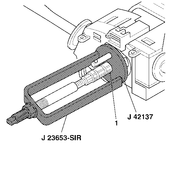
| • | J 23653-SIR Steering Column Lock Plate Compressor |
| • | J 42137 Steering Column Lock Plate Adapter Compressor Adapter |
Removal Procedure
- Disable the SIR system. Refer to SIR Disabling and Enabling in SIR.
- Remove the SIR coil. Refer to Inflatable Restraint Steering Wheel Module Coil Replacement .
- Remove and dispose of the bearing retainer (1) using J 23653-SIR and J 42137 .
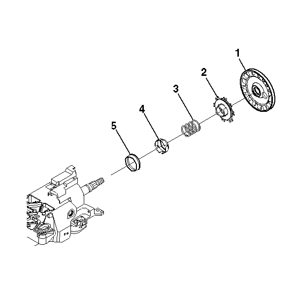
- Remove the shaft lock shield assembly (1).
- Remove the turn signal cancel cam assembly (2).
- Remove the upper bearing spring (3).
- Remove the upper bearing inner race seat (4).
- Remove the inner race (5).
Caution: Refer to SIR Caution in the Preface section.

Important: Do not remove the wire harness straps unless necessary.

Installation Procedure
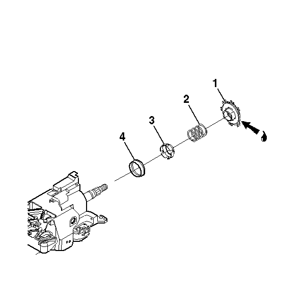
- Install the inner race (4).
- Install the upper bearing inner race seat (3).
- Install the upper bearing spring (2).
- Lubricate the turn signal cancel cam assembly (1) with GM P/N 12377900 (Canadian P/N 10953529).
- Install the turn signal cancel cam assembly (1).
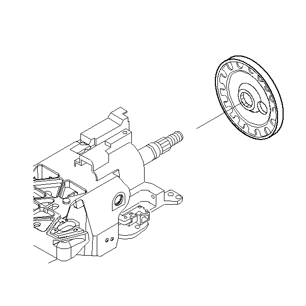
- Install the shaft lock shield assembly.
- Install the new bearing retainer (1) using J 23653-SIR and J 42137 .
- Install the SIR coil. Refer to Inflatable Restraint Steering Wheel Module Coil Replacement .
- Enable the SIR system. Refer to SIR Disabling and Enabling in SIR.

Important: The electrical contact of the turn signal and multifunction switch assembly must rest on the turn signal cancel cam assembly.


Caution: Improper routing of the wire harness assembly may damage the inflatable restraint steering wheel module coil. This may result in a malfunction of the coil, which may cause personal injury.
