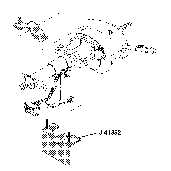
For 1990-2009 cars only
Tools Required
J 41352 Modular Column Holding Fixture
Removal Procedure
- Disable the SIR system. Refer to SIR Disabling and Enabling in SIR.
- Remove the tilt lever from the upper trim cover. Refer to Steering Column Tilt Spring Replacement .
- Remove the steering wheel from the steering column. Refer to Steering Wheel Replacement .
- Remove the steering column from the vehicle. Refer to Steering Column Replacement .
- Check the steering column for accident damage. Refer to Steering Column Accident Damage Inspection .
- Place the bottom of J 41352 into a vise.
- Set the steering column in the bottom of J 41352 .
- Place the top piece of J 41352 onto the column and secure with 2 screws.
- Gently remove the closeout trim cover from the lower trim cover (1).
- Remove 2 pan head tapping screws (2) from the lower trim cover (1).
- Remove the lower trim cover (1).
- Remove 1 TORX® head screw (3) from the upper trim cover (1).
- Remove the upper trim cover (1) with the closeout trim cover (2).
- If necessary, remove the closeout trim cover (2) from the upper trim cover (1).
Caution: Refer to SIR Caution in the Preface section.

Important: Place the steering column in the center position.


Installation Procedure
- If necessary, install the closeout trim cover (2) onto the upper trim cover (1).
- Install the upper trim cover (1) with the closeout trim cover (2) and secure by using 1 TORX® head screw (3).
- Install the lower trim cover (1).
- Connect the lower trim cover (1) to the closeout trim cover.
- Install 2 pan head tapping screws (2).
- Remove 2 screws from the top piece of J 41352 .
- Take the column out from J 41352 .
- Remove the bottom piece of J 41352 from the vise.
- Remove the steering column and J 41352 from the vise.
- Install the steering column into the vehicle. Refer to Steering Column Replacement .
- Install the steering wheel onto the steering column. Refer to Steering Wheel Replacement .
- Install the tilt lever. Refer to Tilt Lever Replacement .
- Enable the SIR system. Refer to SIR Disabling and Enabling in SIR.

Notice: Refer to Fastener Notice in the Preface section.

Tighten
Tighten the screw to 1.5 N·m (13 lb in).

Tighten
Tighten the screws to 3.5 N·m (31 lb in).

Caution: Improper routing of the wire harness assembly may damage the inflatable restraint steering wheel module coil. This may result in a malfunction of the coil, which may cause personal injury.
