Camshaft Cover Replacement Left
Removal Procedure
Tools Required
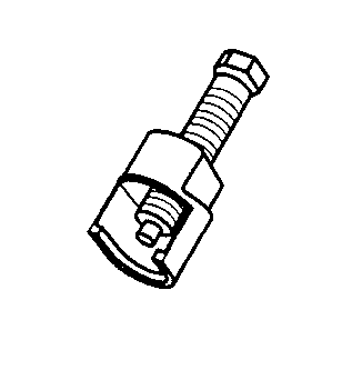
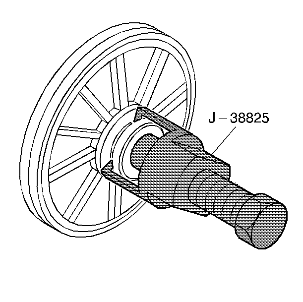
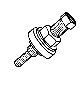
J 38825 Water Pump Drive Pulley Remover
- Disconnect the negative battery cable.
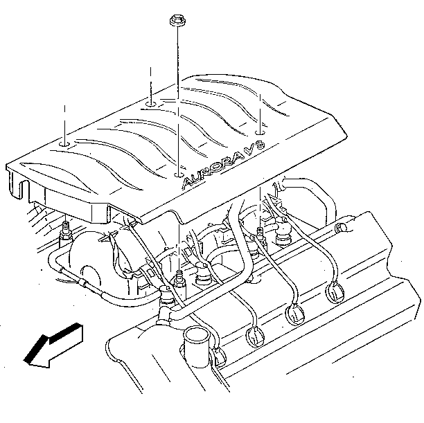
- Remove the intake manifold sight shield.
- Raise the vehicle. Refer to Lifting and Jacking the Vehicle in General Information.
- Partially drain the cooling system. Refer to Cooling System Draining and Filling in Engine Cooling.
- Remove the oil level indicator and tube.
- Disconnect the upper radiator hose at the radiator.
- Disconnect the spark plug wires on the left hand cylinder head and move aside.
- Remove the upper tie-bar assembly.
- Remove the PCV fresh air tube from the camshaft cover.
- Remove the air cleaner outlet duct.
- Remove the EGR outlet pipe.
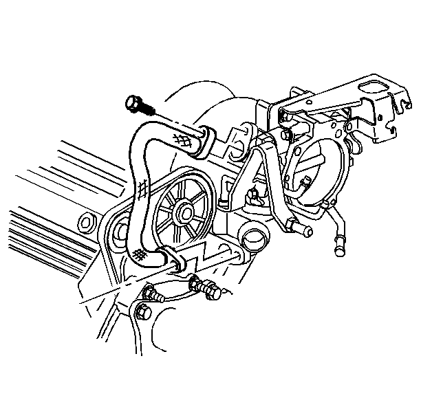
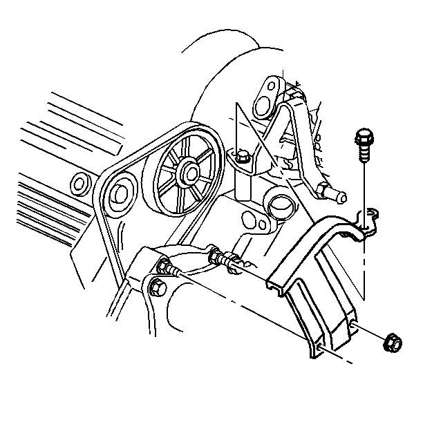
- Remove the water pump drive belt shield retaining nuts and bolts.
- Remove the water pump drive belt shield.
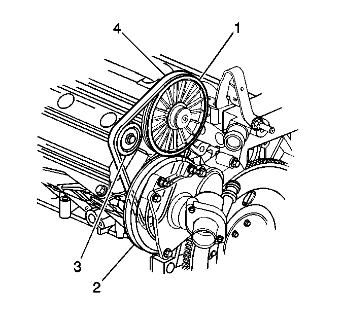
- Remove the water pump drive belt by compressing the belt tensioner (1) while sliding the belt off the drive pulley.
- Remove the water pump drive belt tensioner.
- Remove the water pump drive pulley from the intake camshaft. Use the J 38825 .
- Remove the camshaft seal retaining screws and the seal.
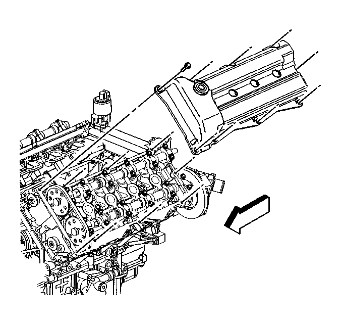
- Remove the camshaft cover bolts.
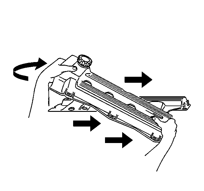
- Remove the camshaft cover using the following steps:
- Lift up the front of the cover approximately 10 inches.
- Lift the rear exhaust edge while holding the front suspended.
- Swing the front of the cover over the intake manifold while sliding the entire cover over the end of the camshaft.
- The camshaft cover seals (perimeter and sparkplug) should be reused unless they are damaged or if the perimeter seal is pulled from its groove during removal.
Caution: Unless directed otherwise, the ignition and start switch must be in the OFF or LOCK position, and all electrical loads must be OFF before servicing any electrical component. Disconnect the negative battery cable to prevent an electrical spark should a tool or equipment come in contact with an exposed electrical terminal. Failure to follow these precautions may result in personal injury and/or damage to the vehicle or its components.


Installation Procedure
Tools Required
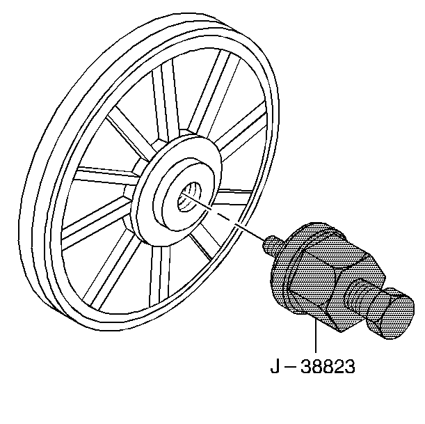
J 38823 Water Pump Drive Pulley Installer
- Install new spark plugs if required.
- Install a new camshaft cover seal if required.
- Place the camshaft cover on the cylinder head using the following procedure:
- Install the camshaft cover bolts.
- Lubricate the camshaft seal lips with engine oil.
- Push the camshaft seal into position around the intake camshaft.
- Coat the seal retaining screws with sealant, GM P/N 1052080, or equivalent. Install the screws.
- Install the water pump pulley on the intake camshaft using the J 38823 .
- Install the water pump drive belt tensioner
- Compress the drive belt tensioner (3). Feed the drive belt around the camshaft pulley (1).
- Check the drive belt for proper seating.
- Install the water pump drive belt shield.
- Install the water pump shield retaining nuts and bolts.
- Install the EGR outlet pipe.
- Connect the upper radiator hose.
- Connect the air intake hose.
- Install the PCV fresh air tube.
- Connect the spark plug wires.
- Install the upper tie bar assembly.
- Raise the vehicle. Refer to Lifting and Jacking the Vehicle in General Information.
- Install the oil level tube and indicator.
- Lower the vehicle.
- Refill the cooling system. Refer to Cooling System Draining and Filling in Engine Cooling.
- Install the intake manifold sight shield.
- Connect the negative battery cable.

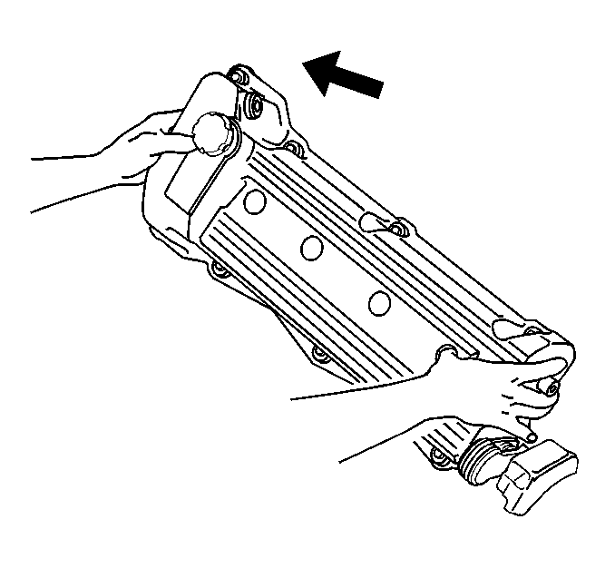
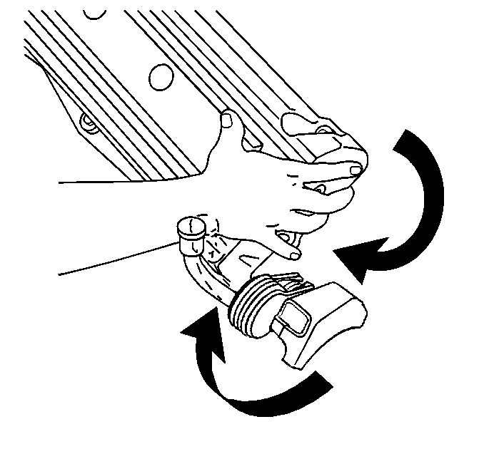
| 3.1. | Insert the intake camshaft end through the hole in the end of the camshaft cover. |
| 3.2. | Using your fingers, guide the camshaft cover up over the edge of the cylinder head. Be careful not to damage the exposed section of the camshaft cover seal on the edge of the cylinder head. |
| 3.3. | Work the camshaft cover into position by pivoting the cover down and to the left allowing the cover to clear the camshaft drive chain and then aligning the bolt holes. |
Notice: Use the correct fastener in the correct location. Replacement fasteners must be the correct part number for that application. Fasteners requiring replacement or fasteners requiring the use of thread locking compound or sealant are identified in the service procedure. Do not use paints, lubricants, or corrosion inhibitors on fasteners or fastener joint surfaces unless specified. These coatings affect fastener torque and joint clamping force and may damage the fastener. Use the correct tightening sequence and specifications when installing fasteners in order to avoid damage to parts and systems.
Tighten
Tighten the bolts to 10 N·m (89 lb in).
Tighten
Tighten the camshaft cover seal screws to 3 N·m (27 lb in).
Tighten
Tighen tensioner to 10 N·m (89 lb in).
Feed the water pump drive belt (4) around the water pump pulley (2) and the water pump drive belt tensioner (3).
Tighten
Tighten the water pump shield retaining nuts to 10 N·m
(89 lb in).
Camshaft Cover Replacement Right
Removal Procedure
- Disconnect the negative battery cable.
- Remove the intake manifold sight shield.
- Disconnect the cruise stepper moter and bracket and set aside.
- Disconnect the ignition system wiring connectors and spark plug wires from the spark plugs.
- Remove the ignition system retaining bolts.
- Remove the ignition system assembly with the spark plug wires attached.
- Remove the PCV valve.
- Remove the fuel vapor canister purge solenoid from the right cover.
- Raise the vehicle. Refer to Lifting and Jacking the Vehicle in General Information.
- Remove the electrical connectors from the vehicle speed sensor (VSS).
- Remove the electrical connectors from the power steering pressure switch (PSP).
- Lower the vehicle.
- Remove the wiring harness retainers from the cover.
- Remove the camshaft cover bolts.
- Remove the camshaft cover.
- The camshaft cover seals (perimeter and sparkplug) should be reused unless they are damaged or if the perimeter seal is pulled from its groove during removal.
Caution: Unless directed otherwise, the ignition and start switch must be in the OFF or LOCK position, and all electrical loads must be OFF before servicing any electrical component. Disconnect the negative battery cable to prevent an electrical spark should a tool or equipment come in contact with an exposed electrical terminal. Failure to follow these precautions may result in personal injury and/or damage to the vehicle or its components.

Installation Procedure
- Install new spark plugs if required.
- Install new camshaft cover seals if required.
- Place the right camshaft cover in position on the cylinder head by aligning the bolt holes.
- Install the camshaft cover bolts.
- Install the fuel vaper canister purge solenoid on to the cam cover.
- Install the canister purge retaining bolt.
- Install the wiring harness retainers to the camshaft cover.
- Raise the vehicle. Refer to Lifting and Jacking the Vehicle in General Information.
- Install the electrical connectors onto the power steering pressure switch (PSP).
- Install the electrical connectors onto the vehicle speed sensor (VSS).
- Lower the vehicle.
- Install the PCV valve.
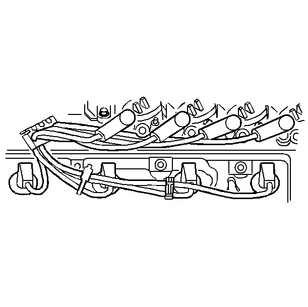
- Install the ignition assembly and spark plug wires onto the right cam cover.
- Route the spark plug wires exactly as shown. If you do not route the wires as shown, a misfire or surge condition could occur.
- Install the ignition system electrical connectors.
- Install the cruise control stepper moter and bracket.
- Install the intake manifold sight shield.
- Connect the negative battery cable.
Notice: Use the correct fastener in the correct location. Replacement fasteners must be the correct part number for that application. Fasteners requiring replacement or fasteners requiring the use of thread locking compound or sealant are identified in the service procedure. Do not use paints, lubricants, or corrosion inhibitors on fasteners or fastener joint surfaces unless specified. These coatings affect fastener torque and joint clamping force and may damage the fastener. Use the correct tightening sequence and specifications when installing fasteners in order to avoid damage to parts and systems.
Tighten
Tighten the camshaft cover bolts to 10 N·m (89 lb in).
Tighten
Tighten the canister purge retaining bolt to 12 N·m (106 lb in).