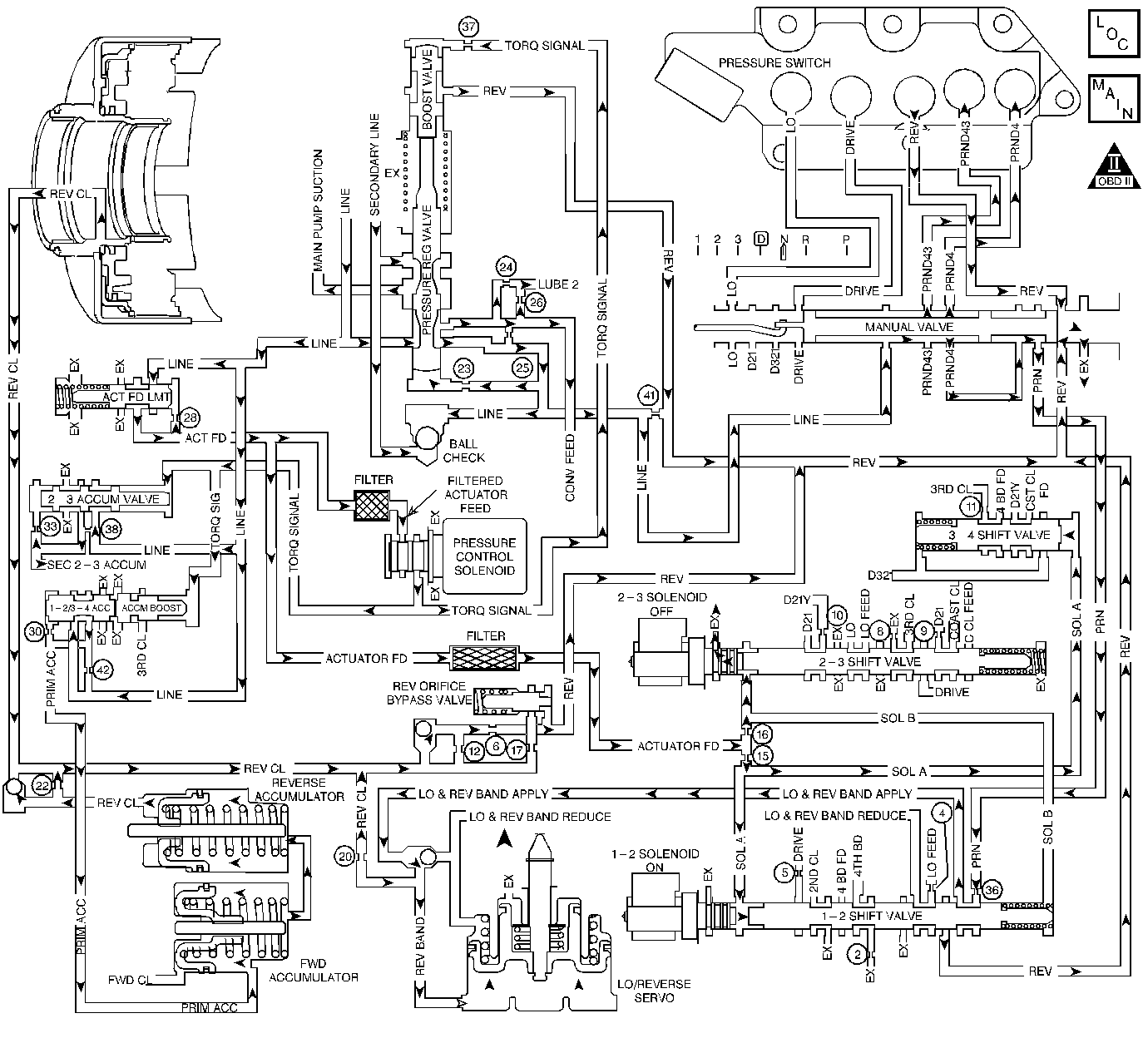
The Powertrain Control Module (PCM) identifies a 2-3 shift solenoid
valve performance condition by monitoring the commanded gear ratio versus
the actual gear ratio.
When the PCM detects the gear ratio outside the limits for a particular
commanded gear, then DTC P0756 sets. DTC P0756 is a Type A DTC.
The numbers below refer to the step numbers on the diagnostic table.
DTC P0756 2-3 Shift Solenoid Valve -- Performance
Step
| Action
| Value(s)
| Yes
| No
|
1
| Was the Powertrain On-Board Diagnostic (OBD) System Check performed?
| --
|
Go to Step 2
| Go to A Powertrain On Board Diagnostic (OBD) System Check
|
2
| Have you performed the fluid checking procedure?
| --
|
Go to Step 3
| Go to
Transmission Fluid Check
|
3
|
- Install the Scan Tool
®.
- With the engine OFF, turn the ignition switch to the RUN position.
Important: Before clearing the DTC(s), use the scan tool in order to record the
Freeze Frame and Failure Records for reference. Using the Clear Info function
will erase the stored Freeze Frame and Failure Records from the PCM.
- Record the DTC Freeze Frame and Failure Records, then clear the DTC(s).
- Using the scan tool, enter the Shift Transmission function.
- Monitor the following data pairs:
- Accelerate the vehicle and command First gear.
Is the gear ratio within the specified parameters?
| 0.65-0.71
|
Go to Step 4
|
Go to Step 5
|
4
|
- Inspect the following items:
| • | A damaged Lo/Rev servo apply pin |
| • | A stuck 2-3 shift valve |
| • | Damaged or leaking oil seals (support seals) |
| • | The support stud from the case to the forward clutch is damaged
or broken |
| • | The Lo roller clutch assembly is worn or damaged |
| • | The forward clutch piston is damaged or cracked |
| • | The forward clutch piston seals are rolled, cut or damaged |
| • | The forward sprag is damaged or not holding |
| • | Check ball #8 is missing |
- Repair or replace any malfunctioning component.
Refer to Unit Repair.
Is the inspection and repair complete?
| --
|
Go to Step 11
| --
|
5
| Accelerate the vehicle and command a 1-2 upshift.
Is the gear ratio within the specified parameters?
| 0.95-1.05
|
Go to Step 6
|
Go to Step 7
|
6
|
- Inspect the following items:
| • | The 2nd clutch plates are burned or damaged |
| • | The 2nd clutch pistons assembly is cracked or damaged |
| • | The 2nd clutch return spring and retainer assembly is broken or
out of position |
| • | The 2nd clutch piston seals are rolled, damaged or leaking |
| • | The 2-3 shift valve is stuck |
- Repair or replace any malfunctioning component.
Refer to Unit Repair.
Is the inspection and repair complete?
| --
|
Go to Step 11
| --
|
7
| Accelerate the vehicle and command a 2-3 upshift.
Is the gear ratio within the specified parameters?
| 1.54-1.71
|
Go to Step 8
|
Go to Step 9
|
8
|
- Inspect the following items:
| • | The 3-4 shift valve bore plug is misassembled |
| • | The exhaust valve cup plug or the exhaust valve are improperly
installed on the driven sprocket support |
| • | The 3rd clutch plates are burned or the splines are damaged |
| • | The 3rd clutch piston is cracked or damaged, or the checkball
is damaged |
| • | The 3rd clutch seals on piston are cut or rolled |
| • | The checkballs (437) are missing or stuck |
| • | Debris in the 2-3 Shift Solenoid Valve |
- Repair or replace any malfunctioning component.
Refer to Unit Repair.
Is the inspection and repair complete?
| --
|
Go to Step 11
| --
|
9
| Accelerate the vehicle and command a 3-4 upshift.
Is the gear ratio within the specified parameters?
| 2.87-3.11
|
Go to Step 10
| Go to Diagnostic Aids
|
10
|
| • | Inspect the following items: |
| • | Debris in the 2-3 Shift Solenoid Valve |
| • | The 4th band is burned, slipping or missing |
| • | The 4th servo pin is broken or seized |
| • | The 4th servo cover seal is rolled, cut or damaged |
| • | The 4th servo piston seal is rolled, cut or damaged |
| • | The 4th servo cover is cracked |
| • | The 3-4 shift valve bore plug is misassembled |
| • | Repair or replace any malfunctioning component. |
Refer to unit repair
Is the inspection and repair complete?
| --
|
Go to Step 11
| --
|
11
| In order to verify your repair, perform the
following procedure:
- Select DTC.
- Select Clear Info.
- Operate the vehicle under the following conditions:
| 3.1. | Road test the vehicle with the gear select lever in D4. |
| 3.2. | Ensure that all four gears are achieved. |
- Select Specific DTC. Enter DTC P0756.
Has the test run and passed?
| --
| System
OK
|
Begin the diagnosis again. Go to Step 1
|

