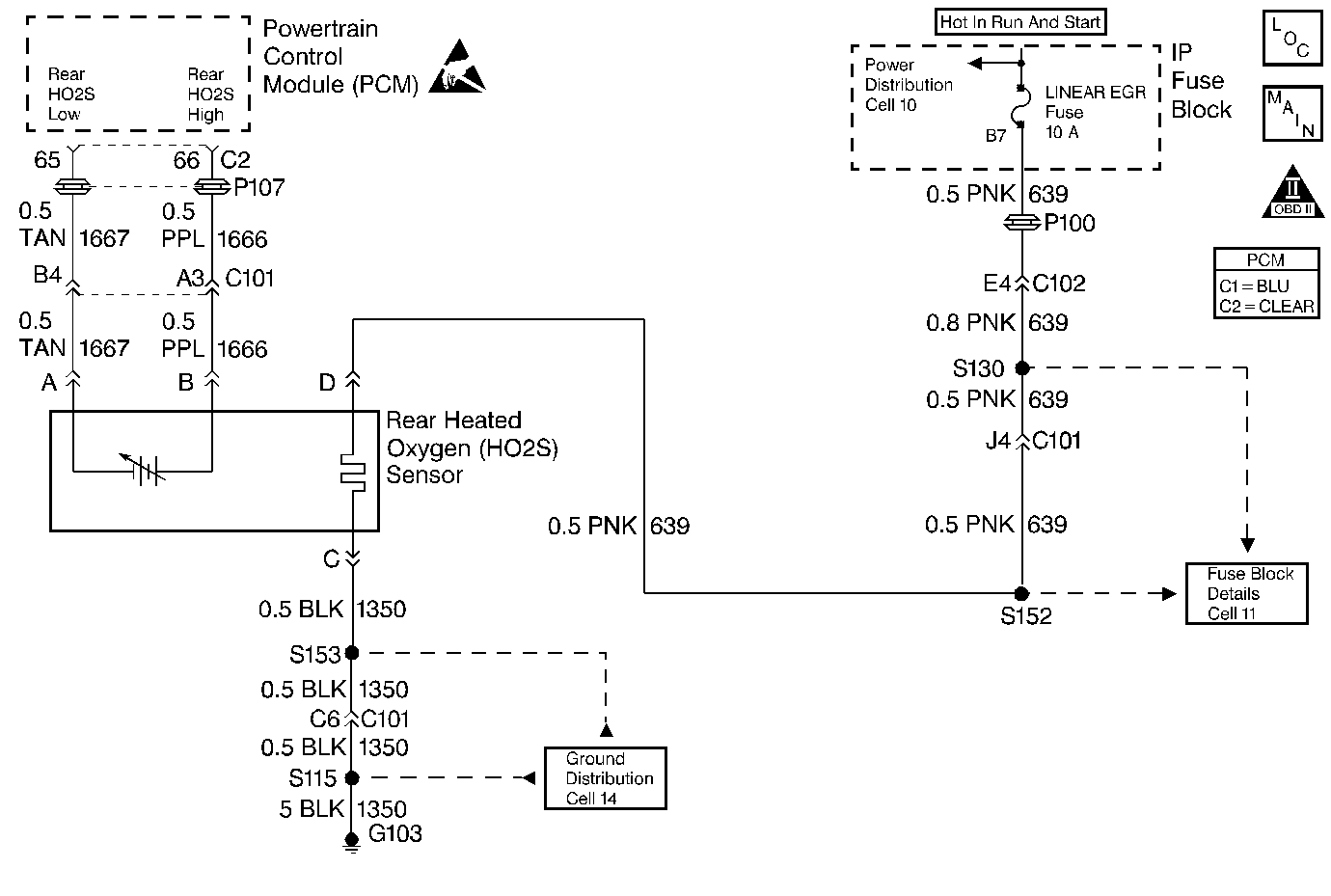
Circuit Description
This diagnostic test is used to determine if the heating element in the rear oxygen sensor is operating properly. An oxygen sensor acts as a battery because it creates its own voltage once it reaches operating temperature. This voltage is produced when the oxygen content in the exhaust stream is different than that in the atmosphere. The heating element is energized through CKT 639 when the ignition is ON and allows the oxygen sensor to reach operating temperature quickly. This in turn allows the PCM to enter Closed Loop fuel control quicker. When cold the voltage that the PCM measures on the O2 sensor HI and LOW inputs is called bias voltage. If it takes too long for the O2 sensor to very above or below the bias voltage within a specific time since key ON DTC P0135 will set.
Conditions for Setting the DTC
Test Conditions
| • | DTCs P0101, P0102, P0103, P0117, P0118, and P0134 not set. |
| • | Engine coolant temperature dropped at least 10°C (50°F) from the end of the last ignition cycle to the beginning of this ignition cycle. |
| • | Ignition voltage 11 volts or more. |
| • | Average rear heated oxygen sensor bias voltage between 352 mv and 546 mv. |
| • | Engine did not stall during test. |
Failure Condition
The PCM monitors the rear heated oxygen sensor input to determine when its voltage becomes either 151 millivolt less than or 151 millivolt greater than average rear heated oxygen sensor bias voltage for 0.1 second. If it takes too long, DTC P0135 will set.
Action Taken When the DTC Sets
| • | The PCM will turn the MIL OFF after three consecutive drive trips that the diagnostic runs and does not fail. |
| • | A Last Test Failed DTC will clear when the diagnostic runs and does not fail. |
| • | A History DTC will clear after forty consecutive warm-up cycles with no failures of any diagnostic test. |
| • | Use a scan tool to clear DTCs. |
| • | Interrupting PCM battery voltage may or may not clear DTCs. This practice is not recommended. Refer to Clearing Diagnostic Trouble Codes in PCM Description and Operation. |
Conditions for Clearing the MIL/DTC
| • | The PCM will turn the MIL OFF after three consecutive drive trips that the diagnostic runs and does not fail. |
| • | A Last Test Failed DTC will clear when the diagnostic runs and does not fail. |
| • | A History DTC will clear after forty consecutive warm-up cycles with no failures of any diagnostic test. |
| • | Use a scan tool to clear DTCs. |
| • | Interrupting PCM battery voltage may or may not clear DTCs. This practice is not recommended. Refer to Clearing Diagnostic Trouble Codes in PCM Description and Operation. |
Diagnostic Aids
Notice: Do not solder heated oxygen sensor wires. Soldering the wires will result in the loss of the air reference to the sensor. Refer to Engine Electrical for proper wire and connection repair techniques.
An intermittent open in CKT 639 or 1350 may cause DTC P0135 to set. Additionally, a malfunctioning rear oxygen sensor heater may be the cause.
Notice: Do not solder heated oxygen sensor wires. Soldering the wires will result in the loss of the air reference to the sensor. Refer to Engine Electrical for proper wire and connection repair techniques.
Test Description
Number(s) below refer to the step number(s) on the Diagnostic Table.
Step | Action | Value(s) | Yes | No |
|---|---|---|---|---|
1 | Was the Powertrain On-Board Diagnostic (OBD) System Check performed? | -- | Go to A Powertrain On Board Diagnostic (OBD) System Check | |
2 |
Is the voltage more than the value specified? | 10.5 volts | ||
Is the amperage between the values specified? | 0.9 - 1.5 amps | |||
4 | Measure the voltage from terminal D (harness side) to ground. Is the voltage the same or higher than the value specified? | 10.5 volts | ||
5 | Using Freeze Frame data, operate the vehicle under the same conditions under which the DTC set. Does the DTC reset? | -- | Go to DTC P0133 HO2S Slow Response Bank 1 Sensor 1 | Fault not present. Refer to Diagnostic Aids |
6 | Repair the open in the Bank 1 HO2S ground circuit. Is the repair complete? | -- | Go to Powertrain Control Module Diagnosis for Verify Repair | -- |
7 | Repair the open or short to ground (blown fuse) in the Bank 1 HO2S ignition feed circuit. Is the repair complete? | -- | Go to Powertrain Control Module Diagnosis for Verify Repair | -- |
8 | Replace the heated oxygen sensor. Refer to Heated Oxygen Sensor (HO2S) Replacement (Rear) . Is the replacement complete? | -- | Go to Powertrain Control Module Diagnosis for Verify Repair | -- |
