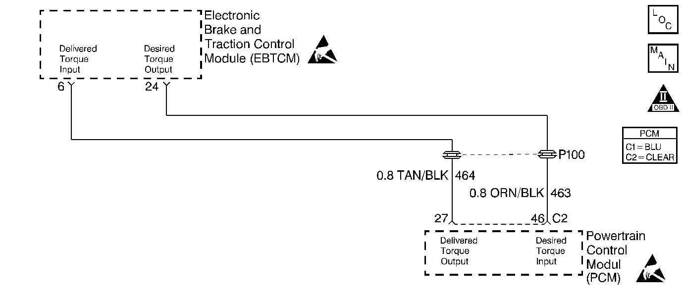
Circuit Description
The PCM contains chips called Output Driver Modules that provide 7 switchable ground outputs for operating solenoids, relays, telltales, and other devices. Each of these ground outputs has an internal fault line that feeds back to the PCM's microprocessor. When the output is OFF, the output driver should receive the 12 volts fed to the solenoid, relay, etc. When the output is ON, it should receive 0 volt since it is grounding the output. If it receives 0 volt when the output is OFF or 12 volts when the output is ON, it sets the fault line low. DTC P1644 is used to monitor the fault line of the delivered torque output to the EBTCM. The EBTCM sends ignition voltage on CKT 464 to the PCM, the PCM will then rapidly pulse CKT 464 to ground creating a Pulse Width Modulated signal that indicates the percentage of torque output the engine is producing. The EBTCM uses this PWM signal for traction control.
Conditions for Setting the DTC
Test Conditions
| • | Brakes not applied. |
| • | PCM in Closed Loop fuel control. |
Failure Condition
Fault line is low for 2.5 seconds
Action Taken When the DTC Sets
| • | The Malfunction Indicator Lamp (MIL) will not illuminate. |
| • | No message will be displayed. |
Conditions for Clearing the DTC
| • | A History DTC will clear after forty consecutive warm-up cycles with no failures of any non-emission related diagnostic test. |
| • | A Last Test Failed (current) DTC will clear when the diagnostic runs and does not fail. |
| • | Use a scan tool to clear DTCs. |
| • | Interrupting PCM battery voltage may or may not clear DTCs. This practice is not recommended. Refer to Clearing Diagnostic Trouble Codes in PCM Description and Operation. |
Diagnostic Aids
Check for an intermittent poor connection at both the PCM and the EBTCM or an open or short in CKT 464.
Step | Action | Value(s) | Yes | No |
|---|---|---|---|---|
1 | Was the Powertrain OBD System Check performed? | -- | Go to A Powertrain On Board Diagnostic (OBD) System Check | |
2 |
Does the display indicate OK continuously? | -- | Fault not present. Refer to Diagnostic Aids | |
3 | Does the display indicate Open? | -- | ||
4 |
Is the voltage the same or more than the value specified? | 10.0 volts | ||
5 |
Is the resistance the same or less than the value specified? | 5 ohms | ||
6 |
Does the Delivered Torque Driver parameter ever display Open/Short? | -- | ||
7 |
Is the voltage more than the value specified? | 0.5 volts | ||
8 | Using DMM J 39200 measure the resistance to ground at PCM connector C2 terminal 27. Is the resistance the same or more than the value specified? | 10K ohms | ||
9 | Repair the open in the Delivered Torque PWM Output circuit. Is the repair complete? | -- | Go to Powertrain Control Module Diagnosis for Verify Repair | -- |
10 | Repair the short to voltage on the Delivered Torque PWM Output circuit. Is the repair complete? | -- | Go to Powertrain Control Module Diagnosis for Verify Repair | -- |
11 | Repair the short to ground on the Delivered Torque PWM Output circuit. Is the repair complete? | -- | Go to Powertrain Control Module Diagnosis for Verify Repair | -- |
12 | Fault is in EBTCM system.
Is the repair and/or replacement complete? | -- | Go to Powertrain Control Module Diagnosis for Verify Repair | -- |
13 |
Was terminal contact repaired? | -- | Go to Powertrain Control Module Diagnosis for Verify Repair | |
14 | Replace the PCM. Refer to PCM Replacement/Programming . Is the replacement complete? | -- | Go to Powertrain Control Module Diagnosis for Verify Repair | -- |
