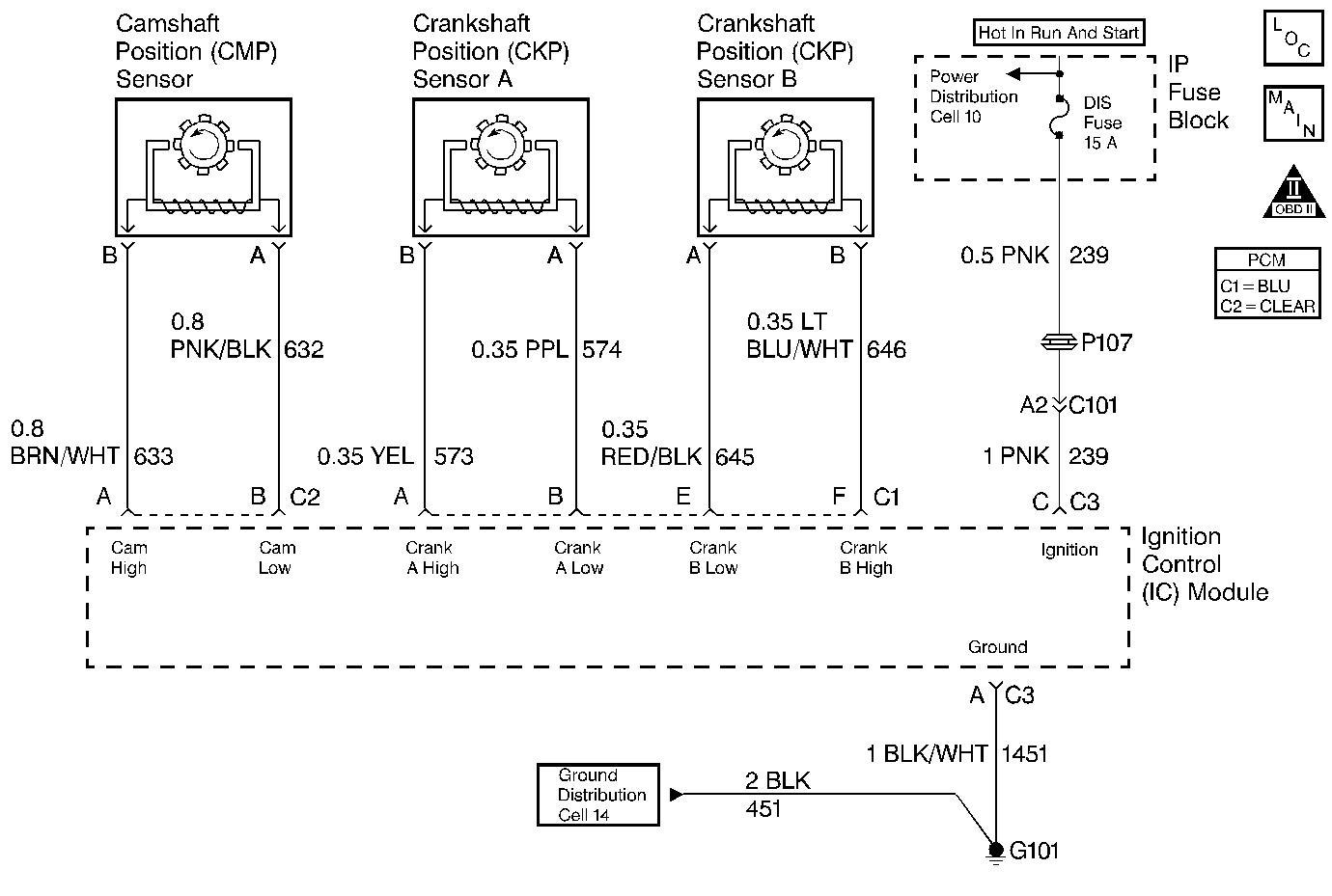
Circuit Description
The diagnostic test checks for CAM reference pulses not received when 4X reference pulses are being received. This indicates a CAM sensor circuit failure and DTC P0340 is set.
Conditions for Setting the DTC
Test Conditions
| • | DTC P0322 not set. |
| • | 4X reference pulses being received. |
| • | Engine speed 1600 RPM or less. |
Failure Condition
A CAM reference pulse was not received for 5.3 seconds.
Action Taken When the DTC Sets
| • | The PCM will illuminate the malfunction indicator lamp (MIL) when the diagnostic runs and fails. |
| • | The PCM will record operating conditions at the time the diagnostic fails. This information will be stored in the Freeze Frame and Failure Records. |
Conditions for Clearing the MIL/DTC
| • | The PCM will turn the MIL OFF after three consecutive drive trips that the diagnostic runs and does not fail. |
| • | A Last Test Failed (current) DTC will clear when the diagnostic runs and does not fail. |
| • | A History DTC will clear after forty consecutive warm-up cycles with no failures of any emission related diagnostic test. |
| • | Use a scan tool to clear DTCs. |
| • | Interrupting PCM battery voltage may or may not clear DTCs. This practice is not recommended. Refer to Clearing Diagnostic Trouble Codes in PCM Description and Operation. |
Test Description
Number(s) below refer to the step number(s) on the Diagnostic Table.
-
Check to see if DTC P1376 is set because a REF LO problem can cause other ignition problems.
-
Checking the resistance of the camshaft position sensor. The resistance should be 800 to 2100 ohms. If the resistance is greater, check for an open or if it is less, check for a short to ground or each other.
-
To ensure acuurate voltage readings, connect the DMM J 39200 to the sensor before recording the Peak Min Max voltage. If the sensor is able to produce a voltage greater than 0.2 volt the sensor is OK. A typical cam sensor should produce an average of 1 volt. Duplicate this test on a known good vehicle to get a comparison voltage if a marginal cam sensor is suspected.
Step | Action | Value(s) | Yes | No |
|---|---|---|---|---|
1 | Was the Powertrain On-Board Diagnostic (OBD) System Check performed? | -- | Go to A Powertrain On Board Diagnostic (OBD) System Check | |
Using a scan tool. Is DTC P1376 also set? | -- | Go to DTC P1376 Ignition Ground Circuit | ||
Is resistance between A and B within the range specified? | 800 - 2100 ohms | |||
4 | Individually measure resistance to ground at both terminal A and B of IC module connector C2. Is resistance at either terminal less than the value specified? | 100 ohms | ||
Is the average AC voltage greater than the value specified? | 0.2 volts | |||
6 | Is resistance less than the value specified? | 800 ohms | ||
7 |
Is resistance greater than the value specified? | 10K ohms | ||
8 |
Is there continuity in both CKT 632 and CKT 633? | -- | ||
9 |
Is the resistance less than the value specified? | 10K ohms | ||
10 | Measure the resistance between PCM connector C2 terminal 4 and IC module connector C4 terminal B. Is the resistance the same or less than the value specified? | 5 ohms | ||
11 |
Does the FREQUENCY measure more than the value specified? | 0.4 Hertz | ||
12 | Repair short to ground in the cam low circuit or the cam high circuit. Is the repair complete? | -- | Go to Powertrain Control Module Diagnosis for Verify Repair | -- |
13 | Repair short between the cam low circuit and the cam high circuit. Is the repair complete? | -- | Go to Powertrain Control Module Diagnosis for Verify Repair | -- |
14 | Repair open or high resistance in the cam low circuit or the cam high circuit. Is the repair complete? | -- | Go to Powertrain Control Module Diagnosis for Verify Repair | -- |
15 | Repair the open in the cam signal circuit. Is the repair complete? | -- | Go to Powertrain Control Module Diagnosis for Verify Repair | -- |
16 | Repair the short to ground in the cam signal circuit. Is the repair complete? | -- | Go to Powertrain Control Module Diagnosis for Verify Repair | -- |
17 |
Was terminal contact repaired? | -- | Go to Powertrain Control Module Diagnosis for Verify Repair | |
18 | Replace the cam sensor. Refer to Camshaft Position (CMP) Sensor Replacement . Is the replacement complete? | -- | Go to Powertrain Control Module Diagnosis for Verify Repair | -- |
19 |
Was terminal contact repaired? | -- | Go to Powertrain Control Module Diagnosis for Verify Repair | |
20 | Replace the Ignition Control module. Refer to Ignition Control Module Replacement (Assembly) . Is the replacement complete? | -- | Go to Powertrain Control Module Diagnosis for Verify Repair | -- |
21 |
Was terminal contact repaired? | -- | Go to Powertrain Control Module Diagnosis for Verify Repair | |
22 | Replace the PCM. Refer to PCM Replacement/Programming . Is the replacement complete? | -- | Go to Powertrain Control Module Diagnosis for Verify Repair | -- |
