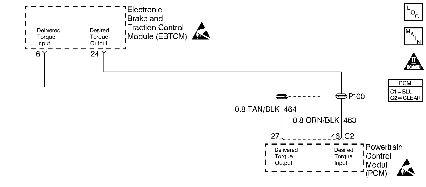
Circuit Description
This diagnostic test checks for a traction control system Pulse Width Modulated signal failure to the PCM. The PCM sends 5 volts on the desired torque circuit (CKT 463) to the Electronic Brake and Traction Control Module (EBTCM). The EBTCM then rapidly switches this CKT to ground creating a PWM, frequency, signal to request a specific amount of torque reduction during a Traction Control Maneuver. If this PWM signal is not received by the PCM for 3 seconds, DTC P1571 is set.
Conditions for Setting the DTC
Test Conditions
| • | DTC P1602 not set. |
| • | Traction control not failed. |
| • | Engine speed greater than 500 RPM for 20 seconds. |
Failure Condition
PWM, frequency, signal not received on desired torque circuit for 3 seconds.
Action Taken When the DTC Sets
| • | PCM disables first gear starts. |
| • | Transaxle shift adapts are maintained at current levels. |
| • | The Malfunction Indicator Lamp (MIL) will not illuminate. |
| • | No message will be displayed. |
Conditions for Clearing the DTC
| • | A History DTC will clear after forty consecutive warm-up cycles with no failures of any non-emission related diagnostic test. |
| • | A Last Test Failed (current) DTC will clear when the diagnostic runs and does not fail. |
| • | Use a scan tool to clear DTCs. |
| • | Interrupting PCM battery voltage may or may not clear DTCs. This practice is not recommended. Refer to Clearing Diagnostic Trouble Codes in PCM Description and Operation. |
Diagnostic Aids
This DTC may set along with several others if the key is held in the CRANK position while the engine is running. The starter lockout function of the PCM is enabled several seconds after the engine is running and will prevent the starter from engaging while the engine is running. This will cause a partial loss of power to some components and systems.
If no fault is present refer to the ABS/TCS FUNCTIONAL TEST in Section 5 to aid in isolating an intermittent fault.
-
The PCM supplies 5 volts on the Desired Torque circuit. A voltage outside of the range indicates a circuit or PCM fault.
-
When shorting the Desired Torque circuit to ground the scan tool will display low desired torque percent for only a few seconds regardless of how long the Desired Torque circuit is shorted to ground.
-
To determine if a short exists between the Desired Torque circuit and another 5 volt circuit (I.E. MAP reference, ECT signal, ect.) disconnect both PCM connectors and measure the resistance between the Desired Torque circuit and all other PCM terminals. Resistance between circuits should measure infinite (OL).
-
When checking for shorts to ground or shorts to other circuits, resistance of more than 10K ohms is usually acceptable although most readings should be infinite (OL).
When checking for circuit continuity (opens) resistance should be 5 ohms or less.
Step | Action | Value(s) | Yes | No |
|---|---|---|---|---|
1 | Did you perform the Powertrain On-Board Diagnostic (OBD) System Check? | -- | Go to A Powertrain On Board Diagnostic (OBD) System Check | |
2 |
Has this DTC failed this ignition? | -- | Fault not present. Refer to Diagnostic Aids | |
Is the voltage within the value range specified? | 4.8 to 5.4 volts | |||
Does the Desired Torque display on the scan tool drop to near 0% torque as the Desired Torque circuit is grounded? | -- | Fault is in the EBTCM system. Refer to EBTCM diagnosis | ||
Was a short found and repaired? | -- | Go to Powertrain Control Module Diagnosis for Verify Repair | ||
6 | Is the voltage measured more than the value specified? | 5.4 volts | ||
Was a circuit fault found and repaired? | -- | Go to Powertrain Control Module Diagnosis for Verify Repair | ||
8 | Repair the short to voltage on the Desired Torque output circuit. Was a circuit fault found and repaired? | -- | Go to Powertrain Control Module Diagnosis for Verify Repair | |
9 |
Was terminal contact repaired? | -- | Go to Powertrain Control Module Diagnosis for Verify Repair | |
10 | Replace the PCM. Refer to PCM Replacement/Programming . Is the replacement complete? | -- | Go to Powertrain Control Module Diagnosis for Verify Repair | -- |
