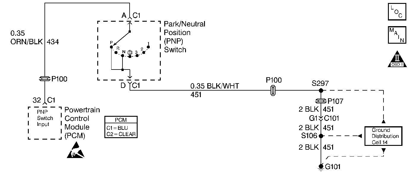
Circuit Description
The Park/Neutral Position (PNP) switch circuit is switched to ground in Park and Neutral. Terminal A of the PNP switch is CKT 434 to the PCM connector C1 terminal 32. Terminal B of the switch is the ground path on CKT 451. This diagnostic test monitors the Park/Neutral switch for a false output. The DTC will set if the switch is indicating park/neutral while the driving conditions present indicate the transaxle is in gear.
Conditions for Setting the DTC
Test Conditions
| • | DTC(s) P0121, P0122, P0123, P0502, P0503 and P0730 not set. |
| • | Engine is running. |
| • | Throttle angle is 10 degrees or more. |
| • | Vehicle speed is 40 MPH or more. |
| • | Delivered torque is 84% or more. |
| • | Gear box ratio is 3.11 or less. |
Failure Condition
P/N is indicated by the Park/Neutral switch/circuit.
Action Taken When the DTC Sets
| • | PCM will substitute park/neutral status from transaxle pressure switch for Park/Neutral Position switch status. |
| • | PCM disables cruise control. |
| • | The Malfunction Indicator Lamp (MIL) will not illuminate. |
| • | No message will be displayed. |
Conditions for Clearing the DTC
| • | A History DTC will clear after forty consecutive warm-up cycles with no failures of any non-emission related diagnostic test. |
| • | A Last Test Failed (current) DTC will clear when the diagnostic runs and does not fail. |
| • | Use a scan tool to clear DTCs. |
| • | Interrupting PCM battery voltage may or may not clear DTCs. This practice is not recommended. Refer to Clearing Diagnostic Trouble Codes in PCM Description and Operation. |
Diagnostic Aids
Manipulate related wiring and connectors while observing the transaxle range switch input. If an intermittent is induced, the parameter display will change.
Attempt to crank the engine while moving the shift lever. Since both the neutral safety and the Park/Neutral Position switch contacts are housed together, an out of adjustment switch could cause an intermittent no-crank condition.
Test Description
Number(s) below refer to the step number(s) on the Diagnostic Table.
-
Checking that switch indicates P/N while in Park.
-
Checking if the P/N Position Input circuit is OK, always shorted or if the switch is possibly out of adjustment.
Step | Action | Value(s) | Yes | No |
|---|---|---|---|---|
1 | Was the Powertrain On-Board Diagnostic (OBD) System Check performed? | -- | Go to A Powertrain On Board Diagnostic (OBD) System Check | |
With the vehicle in Park does the display indicate P/N? | -- | |||
Move the shifter from Park through all the ranges and back to Park while observing the Park/Neutral position parameter. Does the display always indicate P/N? | -- | |||
4 | Does the display match the range selected (P/N when in Park and Neutral and R0D21 in all others)? | -- | Fault not present. Refer to Diagnostic Aids | |
5 | Disconnect the Park/Neutral switch. Does the display indicate P/N? | -- | ||
6 |
Is the resistance less than the value specified? | 10K ohms | ||
7 | Perform the Park/Neutral position switch and shift lever adjustment procedure. Refer to Section 7, 4T80E Automatic Transaxle On-Vehicle Service . Is the adjustment complete? | -- | Go to Powertrain Control Module Diagnosis for Verify Repair | -- |
8 | Repair the short to ground in the Park/Neutral Position Switch input. Is the repair complete? | -- | Go to Powertrain Control Module Diagnosis for Verify Repair | -- |
9 | Replace the Park/Neutral position switch. Refer Section 7, 4T80E Automatic Transaxle On-Vehicle Service . Is the replacement complete? | -- | Go to Powertrain Control Module Diagnosis for Verify Repair | -- |
10 | Replace the PCM. Refer to PCM Replacement/Programming . Is the replacement complete? | -- | Go to Powertrain Control Module Diagnosis for Verify Repair | -- |
