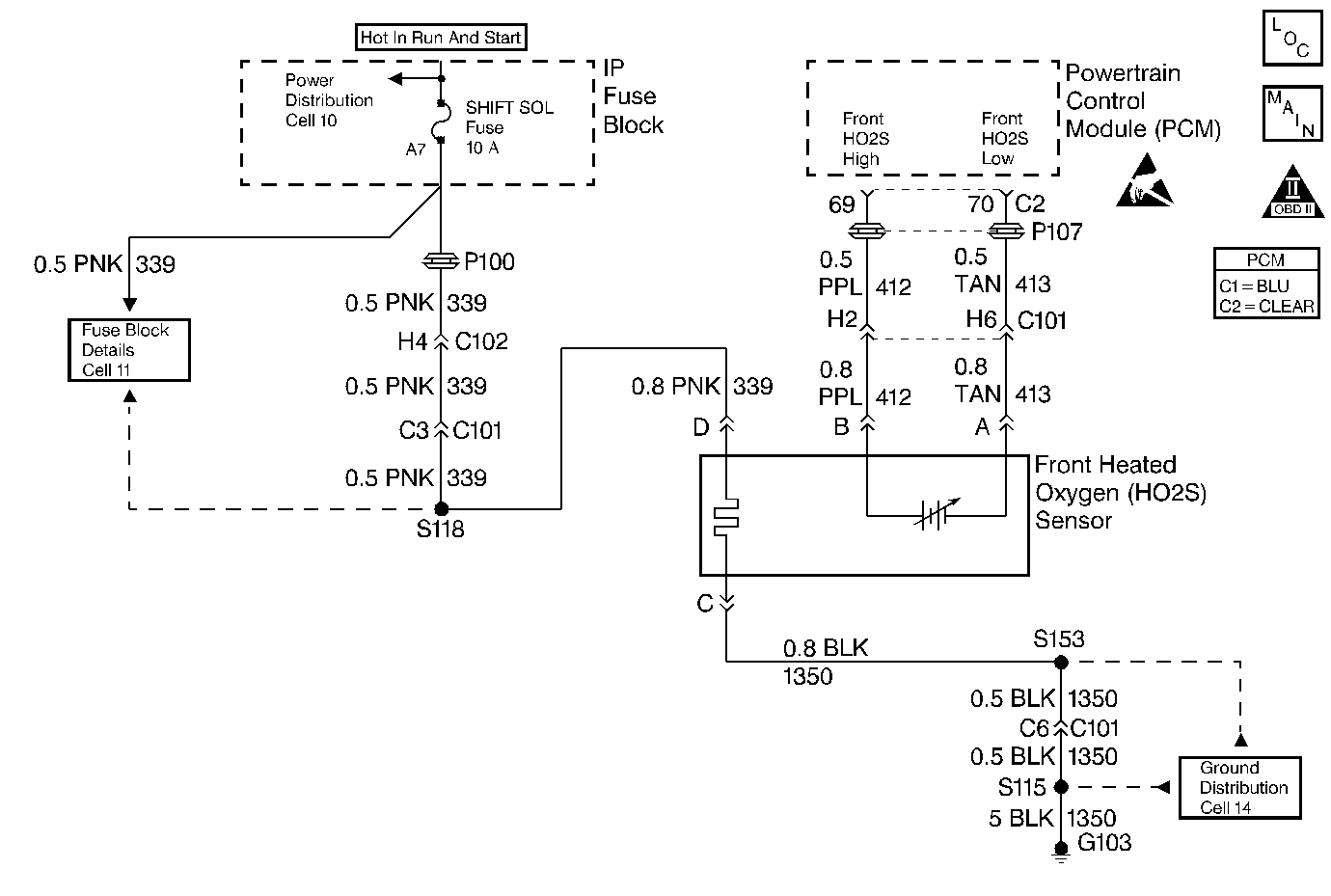
Circuit Description
To provide the best possible combination of driveability, fuel economy and emission control, a Closed Loop air/fuel metering system is used. While in Closed Loop, the PCM monitors the heated oxygen sensor signal voltage and adjust fuel delivery based on signal voltage. A change made to fuel delivery will be indicated by the long and short fuel trim values which can be monitored with a scan tool. Ideal fuel trim values are around 0%; if heated oxygen sensor signal is indicating a lean condition, the PCM will add fuel, resulting in a fuel trim above 0%, 100% is maximum lean. If a rich condition is detected, the fuel trim values will be below 0%, -99% is maximum rich, indicating that the PCM is reducing the amount of fuel delivered. If an excessively rich condition is detected, the PCM will set DTC P0175.
Conditions for Setting the DTC
Test Conditions
| • | DTCs P0101, P0102, P0103, P0106, P0107, P0108, P0121, P0122, P0131, P0132, P0133, P0134, P0137, P0138, P0140, P0143, P0144, P0146, P0151, P0154, P0562, P0163, P0201, P0202, P0203, P0204, P0205, P0206, P0207, P0208, P0300, P0325, P0327, P0340, P0401, P0506, P0507, P1121, P1133, P1153, P1154, P1441, P1508 and P1509 are not set |
| • | Closed loop enabled. |
| • | Engine Coolant Temperature between 84.5°C (184°F) and 105°C (221°F). |
| • | Barometric Pressure greater than 70.8 kPa. |
| • | Mass Air Flow between 3 and 200 grams per second. |
| • | Manifold Absolute Pressure between 27 and 200 kPa. |
| • | Intake Air Temperature between -40°C (-40°F) and 151°C (304°F). |
| • | Engine speed between 400 and 3000 RPM. |
| • | Throttle angle less than 19.8%. |
| • | Vehicle speed less than 70 mph. |
| • | Evap canister purge tank not full (PCM estimation). |
| • | Fuel trim enabled. |
Failure Condition
The PCM detects the average fuel trim cell values are greater than 1.125 for short term fuel trim and 0.992 for long term fuel trim for 2.5 seconds.
Action Taken When the DTC Sets
| • | The PCM will illuminate the malfunction indicator lamp (MIL) when the diagnostic runs and fails. |
| • | The PCM will record operating conditions at the time the diagnostic fails. This information will be stored in the Freeze Frame and Failure Records. |
Conditions for Clearing the MIL/DTC
| • | The PCM will turn the MIL OFF after three consecutive drive trips within the same driving parameters that set the DTC and the diagnostic runs and does not fail. |
| • | A Last Test Failed (current) DTC will clear when the diagnostic runs and does not fail. |
| • | A History DTC will clear after eighty drive cycles within the same driving parameters that set the DTC with no failures of any emission related diagnostic test. |
| • | Use a scan tool to clear DTCs. |
| • | Interrupting PCM battery voltage may or may not clear DTCs. This practice is not recommended. Refer to Clearing Diagnostic Trouble Codes in PCM Description and Operation. |
Diagnostic Aids
If the scan tool indicated the test ran and passed, the fault is not present. If the scan tool indicated that the test did not run, ensure that all the test conditions were met.
Important: An improperly installed air cleaner or a distorted /missing Intake Air Duct may cause this DTC to set. Ensure air cleaner assembly / IA duct is installed correctly and that there are no kinks, folds or damage to the IA Duct or possible debris in the air cleaner assembly or the MAF sensor inlet screen that may distort the air flow.
Test Description
Number(s) below refer to the step number(s) on the Diagnostic Table.
-
Freeze frame data will aid in locating a hard to find malfunction. For example, if the fault only occurs at high speed, this would be determined by monitoring the fuel trim cells. The freeze frame will also indicate how many miles ago the condition was present.
-
If DTC P0172 is also set indicates both banks are operating rich. Inspect items that would cause both banks to operate rich.
Step | Action | Value(s) | Yes | No | ||||||||
|---|---|---|---|---|---|---|---|---|---|---|---|---|
1 | Was the Powertrain On-Board Diagnostic (OBD) System Check performed? | -- | Go to A Powertrain On Board Diagnostic (OBD) System Check | |||||||||
2 | Are any DTCs other than P0171 or P0174 set? | -- | Diagnose other DTCs first | |||||||||
Are either values less than their specified value? | 85°C (185°F) -95% to -98% | |||||||||||
4 |
Has this diagnostic test ran and failed this ignition cycle? | -- | Refer to Diagnostic Aids | |||||||||
Is DTC P0172 also set? | -- | |||||||||||
6 | Visually/physically inspect for the following items:
Was a problem found in any of the above areas? | -- | Refer to Fuel System Diagnosis | |||||||||
7 | Inspect injectors for leaking (Bank 2) or for a fuel pressure regulator leaking fuel into the vacuum hose, refer to Fuel System Diagnosis . When the fuel system check is finished, return to this chart. Was a repair made? | -- | Go to Powertrain Control Module Diagnosis for Verify Repair | |||||||||
8 | Repair or replace any faulty items found. Is the repair completed? | -- | Go to Powertrain Control Module Diagnosis for Verify Repair | -- | ||||||||
9 | Replace the front oxygen sensor. Refer to Heated Oxygen Sensor (HO2S) Replacement (Front) . Is the replacement completed? | -- | Go to Powertrain Control Module Diagnosis for Verify Repair | -- |
