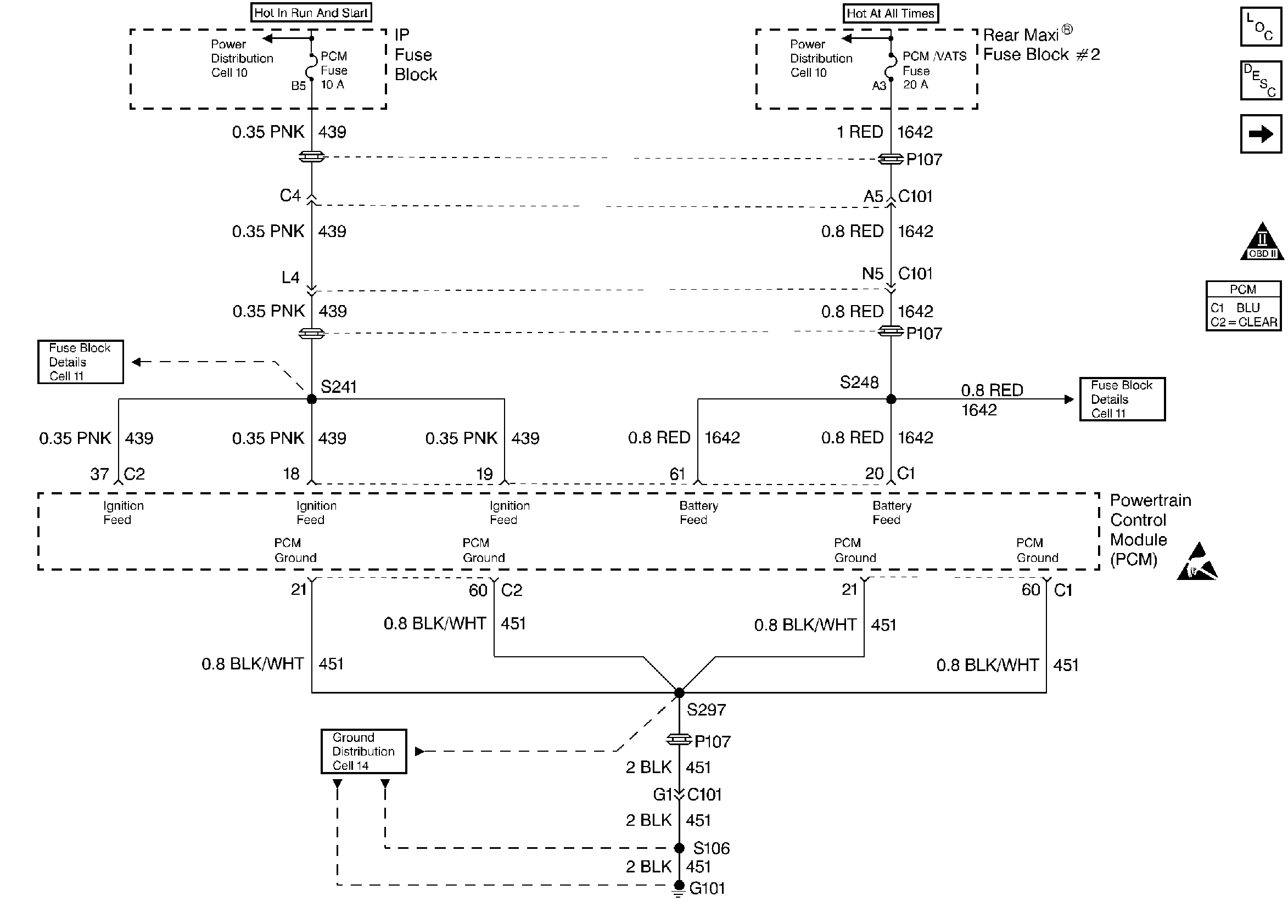
Refer to
PCM Power and Grounds

for wiring view.
Circuit Description
The PCM monitors the system voltage on CKT 439 to PCM connector C1 terminal 19, ignition 1. DTC P0560 will set if this voltage drops below 10 volts, with the engine running above 500 RPM. If the ignition 1 voltage goes to 0 volts, open circuit, the vehicle will not run since the PCM does not have the ignition feed voltage to operate.
Conditions for Setting the DTC
Test Condition
Test continuously.
Failure Condition
Ignition voltage less than 10 volts for 5 seconds with engine speed 500 RPM or greater.
Action Taken When the DTC Sets
| • | PCM disables Evaporative Emission (EVAP) control solenoid. |
| • | PCM disables cruise control. |
| • | PCM disables Torque Converter Clutch (TCC) solenoid. |
| • | PCM disables transaxle pressure control solenoid. |
| • | PCM allows only second gear operation when any forward gear is selected. |
| • | Transaxle shift adapts are maintained at current levels. |
| • | Garage shift adapts are maintained at current levels. |
| • | PCM disables long term fuel trim. |
| • | PCM disables EGR solenoid. |
| • | The Malfunction Indicator Lamp (MIL) will not illuminate. |
| • | The PCM will command a message to be displayed. |
| • | The PCM may record operating conditions at the time the diagnostic fails. This information will be stored in the Failure Records. |
Conditions for Clearing the Message/DTC
| • | The PCM will turn the message OFF after one run and pass of the diagnostic test. |
| • | A History DTC will clear after forty consecutive warm-up cycles with no failures of any non-emission related diagnostic test. |
| • | A Last Test Failed (current) DTC will clear when the diagnostic runs and does not fail. |
| • | Use a scan tool to clear DTCs. |
| • | Interrupting PCM battery voltage may or may not clear DTCs. This practice is not recommended. Refer to Clearing Diagnostic Trouble Codes in PCM Description and Operation. |
Diagnostic Aids
Normal running system voltage is around 15.0 volts. A loose or faulty connection at generator L terminal may cause DTC P0560 to set intermittently.
Test Description
Number(s) below refer to the step number(s) on the Diagnostic Table.
-
If ignition voltage and IPC battery voltage are within 0.5 volt of each other, there may be a system voltage problem. If they are not within 0.5 volt of each other, find out why the PCM is different.
-
Checking if PCM ignition voltage is actually displaying system voltage.
-
Checking for an open or high resistance in the ignition feed circuit.
Step | Action | Value(s) | Yes | No |
|---|---|---|---|---|
1 | Was the Powertrain On-Board Diagnostic (OBD) System Check performed? | -- | Go to A Powertrain On Board Diagnostic (OBD) System Check | |
Are PCM and IPC voltage readings different by more than the value specified? | 0.5 volts | Perform Charging System Check. Go to Section 6, Engine Electrical. Refer to Diagnostic Aids | ||
Using DMM J 39200 measure voltage to ground on the PCM fuse (installed). Are the Ignition 1 and DMM voltage readings different by more than the value specified? | 0.5 volts | Perform Charging System Check. Go to Section 6, Engine Electrical. | ||
Check for high resistance in the ignition feed circuit. Was a high resistance found and repaired? | -- | Go to Powertrain Control Module Diagnosis for Verify Repair | ||
5 |
Was terminal contact repaired? | -- | Go to Powertrain Control Module Diagnosis for Verify Repair | |
6 | Replace the PCM. Refer to PCM Replacement/Programming . Is the replacement complete? | -- | Go to Powertrain Control Module Diagnosis for Verify Repair | -- |
