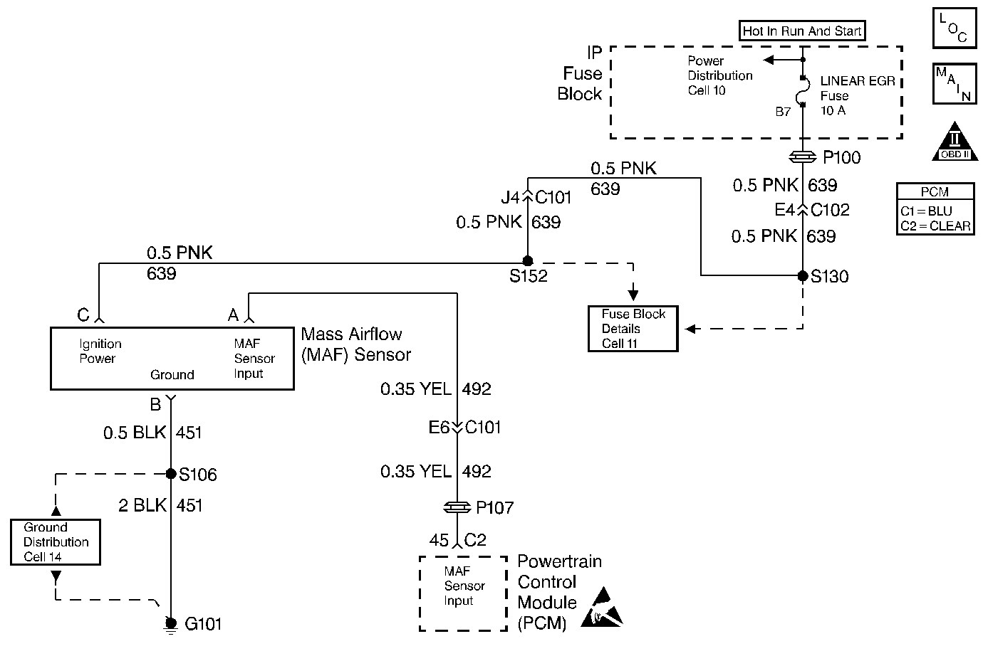
Circuit Description
This diagnostic test is used to determine if a Mass Air Flow sensor circuit failure has occurred by monitoring the MAF signal. The MAF sensor is a high frequency device that measures the rate of air flow through the throttle body. The MAF sensor outputs a series of pulses that vary in frequency with air flow. This signal is used by the PCM for fuel control. MAF readings during acceleration will be much higher than those during deceleration or idle. The PCM reads the MAF sensor input on each 4X ignition reference pulse. If the MAF sensor output drops below 1135 Hz DTC P0102 is set.
Conditions for Setting the DTC
Test Conditions
| • | Engine running. |
| • | Ignition voltage 10.5 volts or more. |
Failure Condition
MAF sensor output frequency is 1135 Hz or less.
Action Taken When the DTC Sets
| • | PCM disables the EVAP control solenoid. |
| • | PCM disables long term fuel trim. |
| • | PCM substitutes calculated MAF value, based on engine speed and throttle position for actual MAF. |
| • | PCM disables torque management. |
| • | PCM maintains transaxle shift adapts at their current levels. |
| • | PCM disables torque converter clutch. |
| • | The PCM will illuminate the malfunction indicator lamp (MIL) when the diagnostic runs and fails. |
| • | The PCM will record operating conditions at the time the diagnostic fails. This information will be stored in the Freeze Frame and Failure Records. |
Conditions for Clearing the MIL/DTC
| • | The PCM will turn the MIL OFF after three consecutive drive trips that the diagnostic runs and does not fail. |
| • | A Last Test Failed (current) DTC will clear when the diagnostic runs and does not fail. |
| • | A History DTC will clear after forty consecutive warm-up cycles with no failures of any emission related diagnostic test. |
| • | Use a scan tool to clear DTCs. |
| • | Interrupting PCM battery voltage may or may not clear DTCs. This practice is not recommended. Refer to Clearing Diagnostic Trouble Codes in PCM Description and Operation. |
Test Description
Number(s) below refer to the step number(s) on the Diagnostic Table.
-
To aid in finding an intermittent, wiggle the MAF sensor connector, PCM connector and the wiring harness while noting the MAF sensor display on a scan tool. With a running engine a reading of 1.3 gms/sec or less would indicate no MAF sensor input to the PCM (an open, short, poor connection or faulty component).
-
If the fuse is blown check for a short to ground or shorted component on the circuit. If the fuse is OK check for voltage at other components on the circuit. If other components have voltage the open is between the splice and MAF sensor. If other components have no voltage the open is between the splice and fuse.
-
A voltage reading of 0 volts would indicate an open circuit or disconnected ground. A voltage reading that is a half volt or more lower than the voltage noted in Step 4 would indicate high circuit resistance or a poor ground connection.
Step | Action | Value(s) | Yes | No |
|---|---|---|---|---|
1 | Was the Powertrain On-Board Diagnostic (OBD) System Check performed? | -- | Go to A Powertrain On Board Diagnostic (OBD) System Check | |
Is MAF sensor reading more than the value specified? | 1.3 gms/sec | Fault not present. Refer to Test Descriptions | ||
3 |
Is the voltage between the values specified? | 4 - 6 volts | ||
4 | With the key ON measure and note the voltage to ground on MAF sensor terminal C. Is the voltage the same or more than the value specified? | 10 volts | ||
5 | With the key ON measure the voltage between MAF sensor terminals B and C. Is the voltage measured within a half volt of the voltage measured in Step 4? | -- | ||
6 |
Was a repair made to the MAF Sensor Input circuit? | -- | Go to Powertrain Control Module Diagnosis for Verify Repair | |
Repair the open or short to ground in the MAF Sensor power feed circuit. Refer to Test Descriptions. Is the repair complete? | -- | Go to Powertrain Control Module Diagnosis for Verify Repair | -- | |
Repair the open or high resistance in the MAF Sensor ground circuit. Refer to Test Descriptions. Is the repair complete? | -- | Go to Powertrain Control Module Diagnosis for Verify Repair | -- | |
9 |
Was terminal contact repaired? | -- | Go to Powertrain Control Module Diagnosis for Verify Repair | |
10 | Replace the Mass Air Flow sensor. Refer to MAF Sensor Replacement . Is the replacement complete? | -- | Go to Powertrain Control Module Diagnosis for Verify Repair | -- |
11 |
Was terminal contact repaired? | -- | Go to Powertrain Control Module Diagnosis for Verify Repair | |
12 | Replace the PCM. Refer to PCM Replacement/Programming . Is the replacement complete? | -- | Go to Powertrain Control Module Diagnosis for Verify Repair | -- |
