SERVICE MANUAL UPDATE SEC. 6E3 REVISED CODE 26 & CHART C-16

SUBJECT: REVISED CODE 26, CHART C-16
MODELS/YEARS: 1992 ACHIEVA W/2.3L (VIN D, A, 3 AND N)
This bulletin cancels and supersedes Service Manual Update 92-U-35 which should be discarded.
This bulletin is being revised to include an updated Code 26 Chart for all 1992 Achieva's equipped with the 2.3L (VIN D, A, and 3) engine. The Chart has been enhanced to incorporate improved diagnostics with the aid of a Tech 1 Scan tool.
This Bulletin has now added an updated CHART C-16 for Achieva's equipped with the 2.3L (VIN D, A, and 3) engine. The revised Chart includes enhanced diagnostics for the "Check Gauges" indicator.
This bulletin updates the Code 26 Chart and Facing page in Section 6E3, "Driveability and Emissions" for 1992 Achieva's equipped with 2.3L (VIN D, A, and 3) engines. This bulletin also updates the Code 26 Chart and facing page (Page 2 of 3), Chart C-16 and facing page for 1992 Achieva's equipped with the 3300 (VIN N) engine. The revised Charts include diagnosis for vehicles equipped with a "Check Gauges" indicator instead of an engine temperature "Temp" indicator.
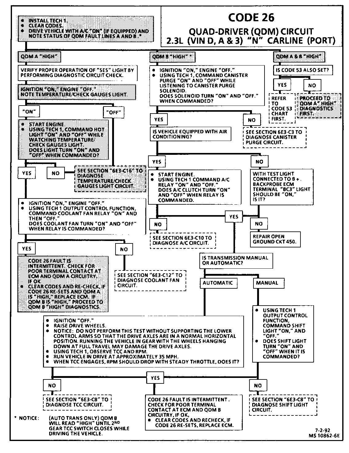
CODE 26 QUAD-DRIVER (QDM) CIRCUIT 2.3L (VIN D, A & 3) "N" CARLINE (PORT)
Circuit Description:
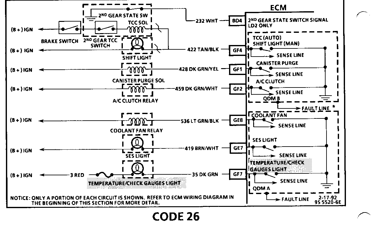
The ECM controls most components with electronic switches which complete a ground circuit when turned "ON." These switches are arranged in groups of 4, called Quad-Driver Modules (QDM's) which can independently control up to 4 outputs (ECM terminals), although not all outputs are used. When an output is "ON," the terminal is grounded and its voltage normally will be low. When an output is "OFF," its terminal voltage normally will be high, except for the TCC, as noted below, which depends on the brake and 2nd gear TCC switches.
QDM's are fault protected. If a relay or solenoid coil is shorted, having very low or zero resistance, or if the control side of the circuit is shorted to voltage, it would allow too much current into the QDM. The QDM senses this and the output turns "OFF" or its internal resistance increases to limit current flow and protect the QDM. The result is high output terminal voltage when it should be low. If the circuit from B + or the component is open, or the control side of the circuit is shorted to ground, terminal voltage will be low, even when output is commanded "OFF." Either of these conditions is considered to be a QDM fault. *See NOTE below!
Each QDM has a separate fault line to indicate the presence of a current fault to the ECM's central processor. A "Scan" tool displays the status of each of these fault lines as "Low" = OK, "High" = Fault*. Because of the brake and 2nd gear switches in the TCC circuit, Code 26 is set under different conditions for QDM A and QDM B as follows:
- QDM A fault line = "High" for 20 seconds or more.
- QDM B fault line = "High" for 20 seconds or more and
- Brake switch signal indicates brake switch is closed and 2nd gear state switch indicates transaxle is in 2nd or 3rd gear.
OR
- TCC is commanded "ON."
*NOTE: (Auto Trans Only) QDM B will read "high" until 2nd gear TCC switch closes while driving the vehicle.
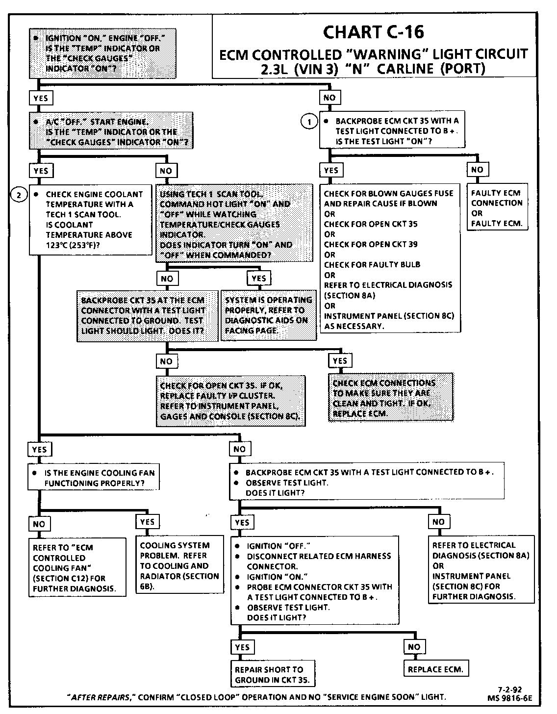
CHART C-16 ECM CONTROLLED "WARNING" LIGHT CIRCUIT 2.3L (VIN D, A & 3) "N" CARLINE (PORT)
Circuit Description:
The "Temp" light or optional "Check Gauges" light, is connected to battery voltage through the ignition switch. The ECM energizes the bulb by supplying a path to ground through "Quad-Driver" module B.
Test Description:
Number(s) below refer to circled number(s) on the diagnostic chart.
1. With the ignition "ON" and engine "OFF," the ECM should be grounding CKT 35.
2. While the engine is running, the "Temp" light or optional "Check Gauges" light should be turned "ON" by the ECM only when the coolant temperature is above 123 degrees C (253 degrees F). The "Temp" light or "Check Gauges" light should be turned "OFF" when the engine is running and the coolant temperature goes lower than 120 degrees C (249 degrees F).
Diagnostic Aids:
The coolant temperature sensor, in rare cases, may fail to indicate the correct engine coolant temperature without setting a malfunction code. This could result in turning "ON" the "Temp" light or optional "Check Gauges" light without having an overheating condition. It could also result in overheating without the "Temp/Check Gauges" light being turned "ON."
An intermittent problem may be caused by a poor or corroded connection, rubbed through wire connection, a wire that is broken inside the insulation, or a corroded wire.
Any circuitry, that is suspected as causing the intermittent complaint, should be thoroughly checked for backed out terminals, improper mating, broken locks, improperly formed or damaged terminals, poor terminal to wiring connections, corroded terminals and/or wiring, or physical damage to the wiring harness.
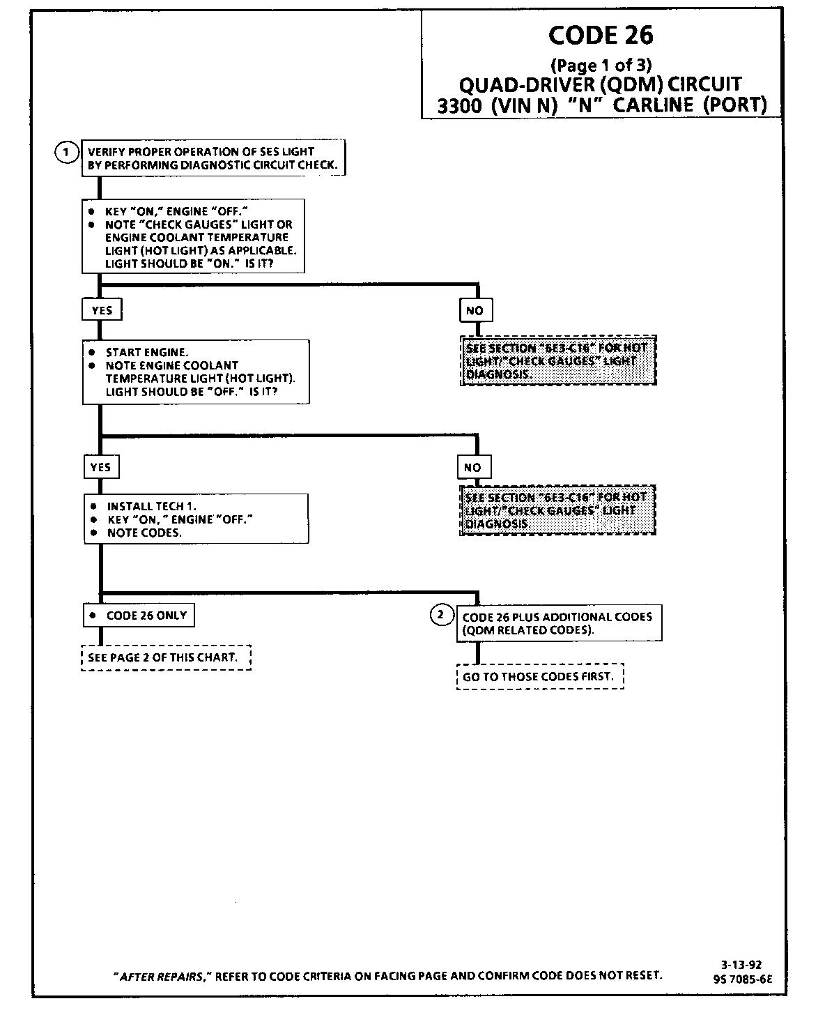
CODE 26 (Page 1 of 3) QUAD-DRIVER (QDM) CIRCUIT 3300 (VIN N) "N" CARLINE (PORT)
Circuit Description:
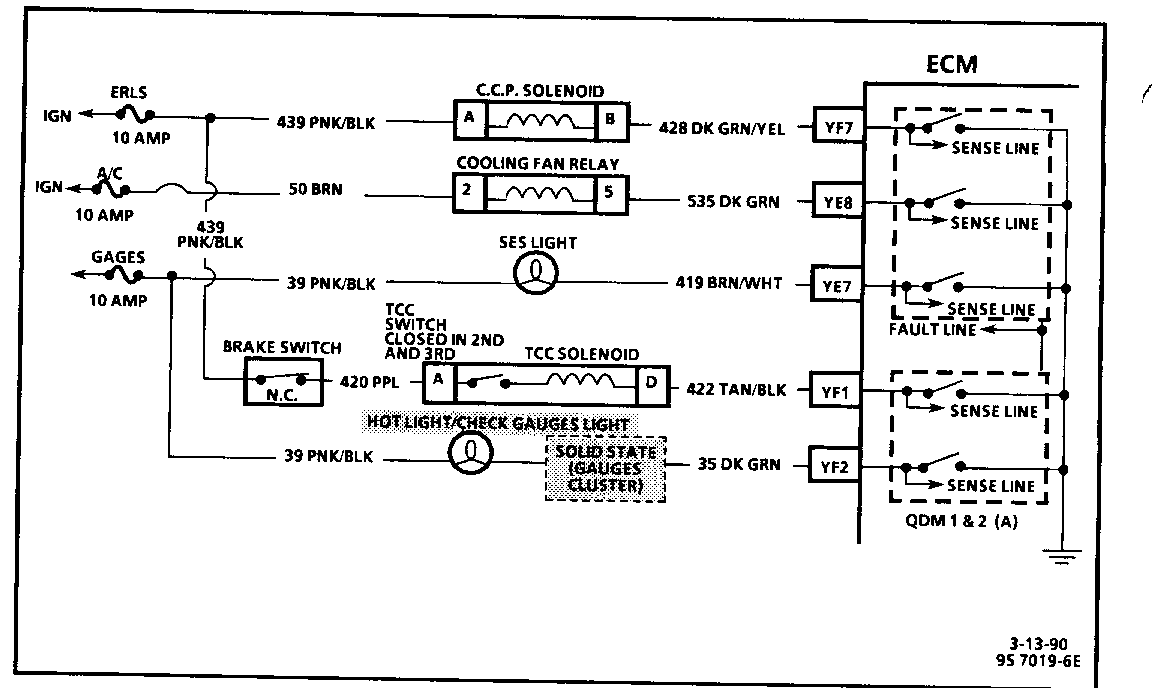
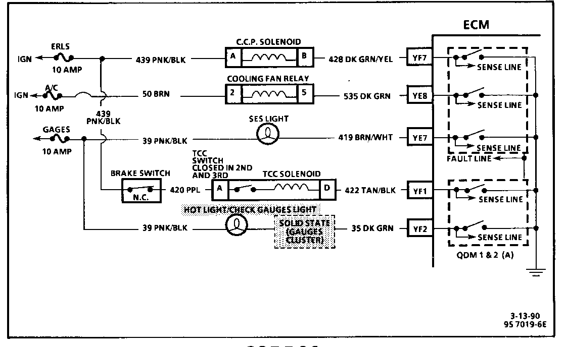
Quad-Driver Modules (QDM) are used to control the components shown in the illustration above. When the ECM is commanding a component "ON," the QDM closes the switch completing the circuit to ground.
Each QDM has a sense line and a fault line. When a component is commanded "ON," the voltage potential on the sense line is low and when the component is commanded "OFF," the voltage potential on the sense line is high.
Code 26 will set when the ECM is commanding a QDM 1 + 2 (A) controlled component "ON" and the voltage potential on the sense line is high, or if the component is commanded "OFF" and the voltage potential on the sense line is low. The fault line, which can be monitored with the Tech 1, will read "HI" under these conditions. If the ECM detects a "HI" QDM 1 + 2 (A) fault line when it expects a "LO" one, it will illuminate the "Service Engine Soon" light and store a Code 26. QDM 3 (B) will not set a Code 26.
Notice: Code 26 will not set even though the fault line scans "HI" under the following conditions:
- Ignition "ON"/engine not running.
OR
- Vehicle not operating in second or third gear.
OR
- Brake applied.
Vehicles with a 3T40 transaxle will read "HI" until the second gear switch is closed. To check, disconnect TCC connector and connect a test light between terminals "A" and "D". This should cause the Tech 1 to display "Lo" for QDM 1 + 2 (A) with the engine running.
Test Description:
Number(s) below refer to circled number(s) on the diagnostic chart.
1. The ECM does not know which controlled circuit caused the Code 26 so this chart will go through each of the circuits to determine which is at fault. This test checks the "Service Engine Soon" light driver and the "Service Engine Soon" light circuit.
2. QDM symptoms:
- TCC-Malfunctioning-Code 39.
- "Check gauges" or Hot Light - "ON" all the time/"OFF" during bulb check.
- Coolant fan "ON" all the time or won't come "ON" at all.
- Poor driveability due to 100% canister purge.
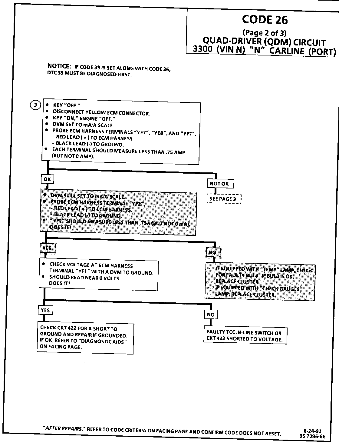
CODE 26 (Page 2 of 3) QUAD-DRIVER (QDM) CIRCUIT 3300 (VIN N) "N" CARLINE (MFI)
Circuit Description:
Quad-Driver Modules (QDM) are used to control the components shown in the illustration above. When the ECM is commanding a component "ON," the QDM closes the switch completing the circuit to ground.
Each QDM has a sense line and a fault line. When a component is commanded "ON," the voltage potential on the sense line is low and when the component is commanded "OFF," the voltage potential on the sense line is high.
Code 26 will set when the ECM is commanding a QDM A controlled component "ON" and the voltage potential on the sense line is high, or if the component is commanded "OFF" and the voltage potential on the sense line is low. QDM B will not set Code 26.
Vehicles with a 3T40 transaxle will read "HIGH" until the TCC in-line switch is closed. To check, disconnect TCC connector and connect a test light between terminals "A" and "D". This should cause the Tech 1 to display "LOW" for QDM A with the engine running.
Test Description:
Number(s) below refer to circled number(s) on the diagnostic chart.
3. This test will determine which circuit is out of specifications.
Diagnostic Aids:
Monitor the voltage at each terminal while moving related harness connectors, including ECM harness. If the failure is induced, the voltage will change. This may help locate the intermittent. Check for bent pins at ECM and ECM connector terminals. Also, ensure that the mid gear switch and CKT 232 is not open with the vehicle operating in park/neutral or 1st gear - This condition can cause a false Code 26 to be set. Refer to Code 27 chart for diagnosis. If code re-occurs with no apparent connector problem, replace ECM.
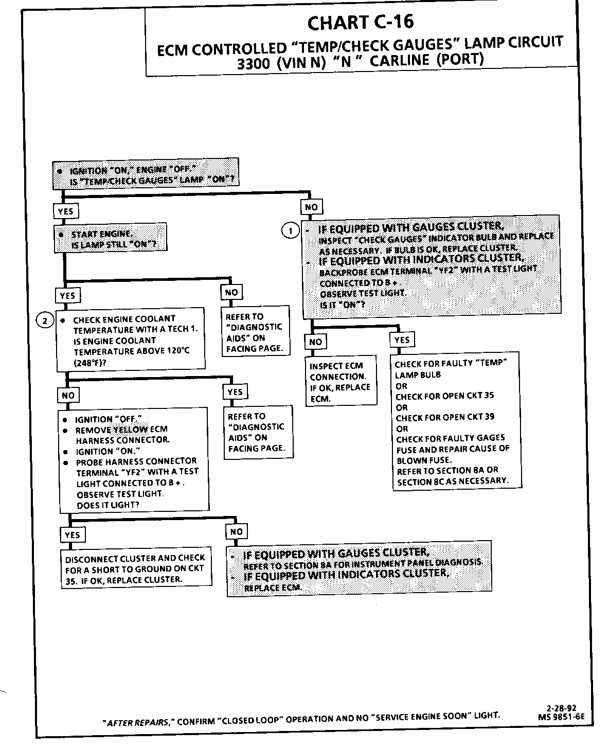
CHART C-16 ECM CONTROLLED "TEMP/CHECK GAUGES" LAMP CIRCUIT 3300 (VIN N) "N" CARLINE (PORT)
Circuit Description:
The "Temp/Check Gauges" lamp is powered through the gages fuse by ignition voltage. The ECM energizes the "Temp" lamp bulb by supplying a path to ground through Quad-Driver module 1 + 2 (A). The "Check Gauges" lamp bulb is energized by a buffer within the cluster if an abnormal condition is present (low fuel level, low oil pressure, high or low system voltage or CKT 35 grounded, indicating high engine coolant temperature.)
Test Description:
Number(s) below refer to circled number(s) on the diagnostic chart.
1. With the ignition "ON" and engine "OFF," the ECM should be grounding CKT 35.
2. The "Temp" lamp should only be "ON" while the engine is running if the coolant temperature is 120 degrees C (248 degrees F) or higher. The "Check Gauges" lamp should be "ON" only if an abnormal condition can be seen on an instrument cluster gauge. If the "Check Gauges" lamp is "ON," and CKT 35 is not grounded, refer to SECTION 8A for instrument panel diagnosis.
Diagnostic Aids:
The coolant temperature sensor, in rare cases, may fail to indicate the correct engine coolant temperature without setting a malfunction code. This could result in turning "ON" the "Temp" lamp without having an overheating condition. It could also result in overheating without the "Temp" lamp being turned "ON." See "Coolant Sensor Temperature vs. Resistance Values" Diagnostic Aids table on Code 15 chart or compare coolant temperature reading on the Tech 1 with actual coolant temperature. Replace coolant temperature sensor if mis-scaled.


General Motors bulletins are intended for use by professional technicians, not a "do-it-yourselfer". They are written to inform those technicians of conditions that may occur on some vehicles, or to provide information that could assist in the proper service of a vehicle. Properly trained technicians have the equipment, tools, safety instructions and know-how to do a job properly and safely. If a condition is described, do not assume that the bulletin applies to your vehicle, or that your vehicle will have that condition. See a General Motors dealer servicing your brand of General Motors vehicle for information on whether your vehicle may benefit from the information.
