Crankshaft and Bearing Cleaning and Inspection Bearing Selection
Tools Required
| • | J 36660-A Torque Angle Meter |
| • | J 8087 Cylinder Bore Gauge |
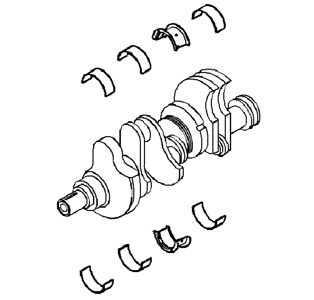
- Clean the crankshaft of the following elements:
- Inspect the crankshaft oil passages for obstructions.
- Inspect the crankshaft keyway for nicks or wear.
- Inspect the crankshaft threads.
- Inspect the crankshaft bearing journals and the crankshaft thrust surfaces for the following conditions:
- Inspect the corresponding crankshaft bearings for embedded foreign material and determine the source.
- Inspect the crankshaft bearings for uneven side-to-side wear. This may indicate a bent crankshaft or a tapered bearing journal.
- The crankshaft bearings are of the precision insert type. The crankshaft bearings are available in standard and various undersizes.
- Inspect the outer surfaces of the crankshaft bearings for the following conditions:
- Inspect the thrust surfaces of the main thrust bearing for the following conditions:
- Inspect the connecting rod bearing bores or crankshaft main bearing bores using the following procedure:
| • | Oil |
| • | Sludge |
| • | Carbon |
Important: If cracks, severe gouges or burned spots are found, the crankshaft must be replaced. Slight roughness may be removed with a fine polishing cloth soaked in clean engine oil. Burrs may be removed with a fine oil stone.
| • | Cracks |
| • | Chips |
| • | Gouges |
| • | Roughness |
| • | Grooves |
| • | Overheating (discoloration) |
Important: Note the location of the crankshaft main bearing high spots. If they are not in line, the crankshaft is bent and must be replaced.
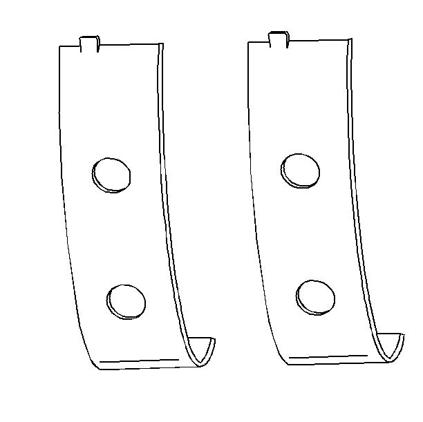
Notice: Do not scrape, shim, or file bearing inserts. If the bearing surface of the insert is touched with bare fingers, the skin oil and acids will etch the bearing surface.
| • | Wear - surface wear indicates either movement of the insert or high spots in the surrounding material (spot wear). |
| • | Overheating or discoloration |
| • | Looseness or rotation indicated by flattened tangs and wear grooves |
| • | Wear |
| • | Grooving (Grooves are caused by irregularities of the crankshaft thrust surface.) |
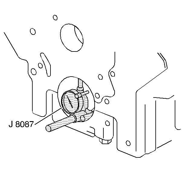
Important: If crankshaft bearing failure is due to other than normal wear, investigate the cause. Inspect the crankshaft or connecting rod bearing bores.
| 11.1. | Tighten the bearing cap to specification. |
| 11.2. | Measure the bearing bore for taper and out-of-round using the J 8087 . No taper or out-of-round should exist. |
Bearing Selection
Measure the bearing clearance to determine the correct replacement bearing insert size. There are two methods to measure bearing clearance. Method A gives more reliable results and is preferred.
| • | Method A yields measurement from which the bearing clearance can be computed. |
| • | Method B yields the bearing clearance directly. Method B does not give any indication of bearing run-out. |
Method A
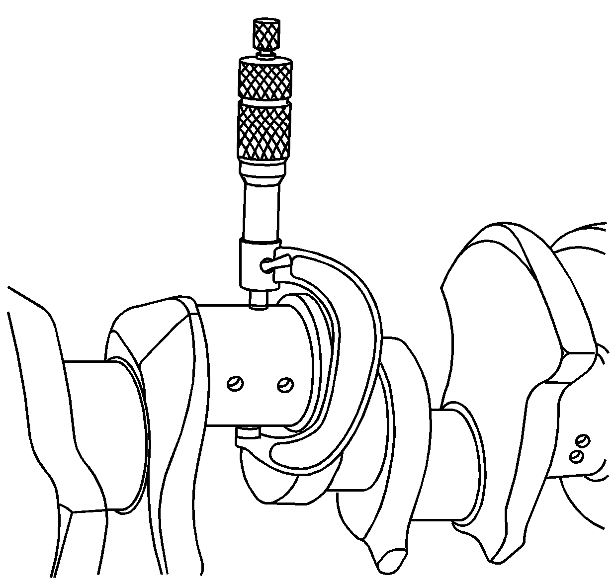
- Measure the crankshaft bearing journal diameter with a micrometer in several places, 90 degrees apart. Average the measurements.
- Measure the crankshaft bearing journal taper and runout.
- Install the crankshaft bearing inserts. Tighten the bearing cap bolts to specification. Refer to Fastener Tightening Specifications.
- Measure the connecting rod inside diameter in the same direction as the length of the rod with an inside micrometer.
- Measure the crankshaft main bearing inside diameter with an inside micrometer.
- Select a set of bearing inserts that will produce the desired clearance.
- If the specified clearances cannot be met, the crankshaft journals must be reconditioned and undersized bearing inserts installed.
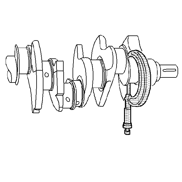
Important: Do not mix inserts of different nominal size in the same bearing bore.
Method B
- Clean the used bearing inserts.
- Install the used bearing inserts.
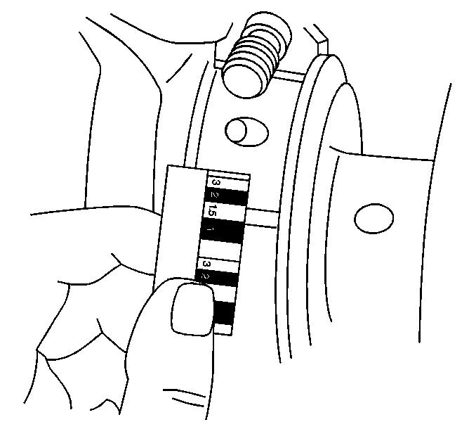
- Place a piece of gauging plastic across the entire bearing width.
- Install the bearing caps.
- Install the bearing cap bolts to specification.
- Remove the bearing cap, leaving the gauging plastic in place. It does not matter whether the gaging plastic adheres to the journal or to the bearing cap.
- Measure the gauging plastic at the widest point with the scale printed on the gaging plastic package.
- Remove the gauging plastic.
- Select a set of bearing inserts that will produce the desired clearance.
Important: Do not mix inserts of different nominal size in the same bearing bore.
Notice: In order to prevent the possibility of cylinder block or crankshaft bearing cap damage, the crankshaft bearing caps are tapped into the cylinder block cavity using a brass, lead, or a leather mallet before the attaching bolts are installed. Do not use attaching bolts to pull the crankshaft bearing caps into the seats. Failure to use this process may damage a cylinder block or a bearing cap.
Important: Do not rotate the crankshaft.
Crankshaft and Bearing Cleaning and Inspection Inspection
Tool Required
J 7872 Magnetic Base Dial Indicator Set
- Remove the clutch pilot bearing.
- Clean the crankshaft with solvent.
- Thoroughly clean all oil passages and inspect for restrictions or burrs.
- Dry the crankshaft with compressed air.
- Perform a visual inspection of the crankshaft for damage.
- Inspect the crankshaft journals for wear (1).
- Inspect the crankshaft journals for grooves or scoring (2).
- Inspect the crankshaft journals for scratches or wear (3).
- Inspect the crankshaft journals for pitting or imbedded bearing material (4).
- Measure the crankshaft journals for out-of-round.
- Measure the crankshaft journals for taper.
- Measure the crankshaft runout.
- Use the J 7872 in order to measure the crankshaft runout at the front and rear intermediate journals.
- Use the J 7872 in order to measure the runout of the crankshaft rear flange.
- Install a new clutch pilot bearing.
- Inspect crankshaft bearings for craters or pockets. Flattened sections on the bearing halves also indicate fatigue.
- Inspect the crankshaft bearings for excessive scoring or discoloration.
- Inspect the crankshaft bearings for dirt or debris imbedded into the bearing material.
- Inspect the crankshaft bearings for improper seating indicated by bright, polished sections of the bearing.
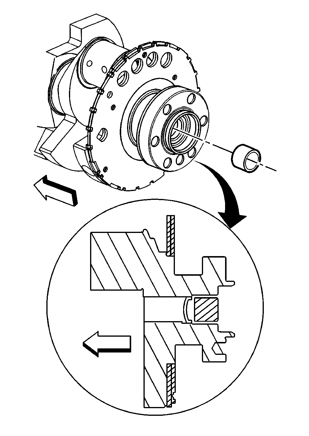
Notice: Use care when handling the crankshaft in order to avoid damaging the bearing surfaces, crankshaft position reluctor ring and crankshaft position reluctor ring teeth. Damage to the crankshaft position reluctor ring or crankshaft position reluctor ring teeth may effect OBD II system performance.
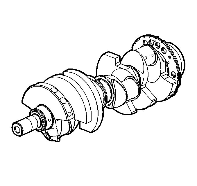
Caution: Wear safety glasses in order to avoid eye damage.
Important: Reluctor ring teeth should not have imperfections on the rising or falling edges.
Imperfections of the reluctor ring teeth may effect OBD II system performance.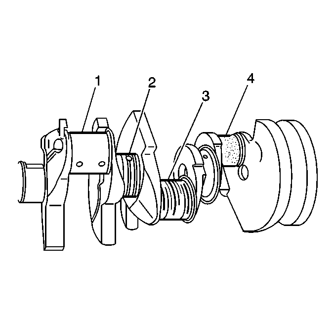
Journals should be smooth with no signs of scoring, wear, or damage.
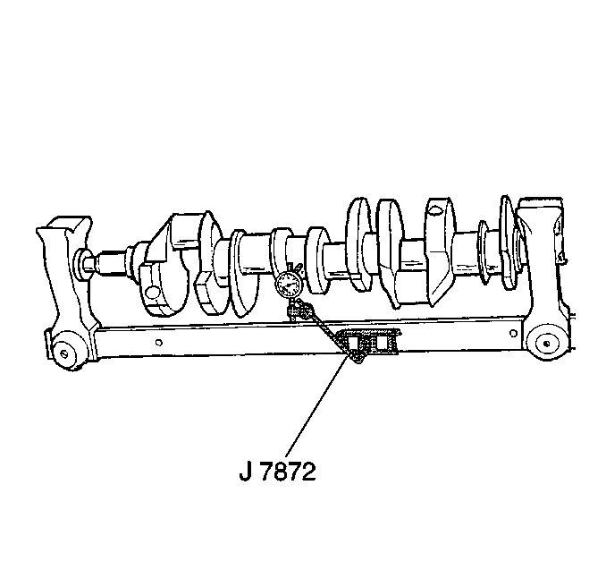
Using wooden V blocks, support the crankshaft on the front and rear journals.
| 14.1. | Compare the measurements to Engine Mechanical Specifications . |
| 14.2. | Replace or repair the crankshaft if the measurements are not within the specifications. |

A properly installed clutch pilot bearing will be installed until flush to the face of the crankshaft.
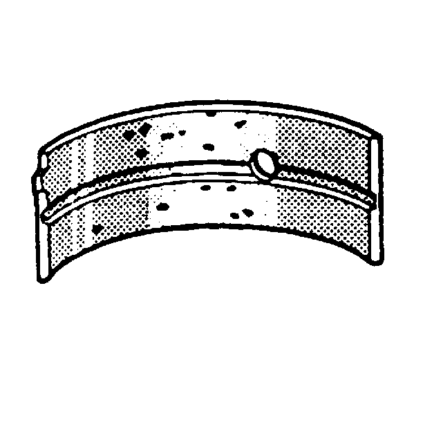
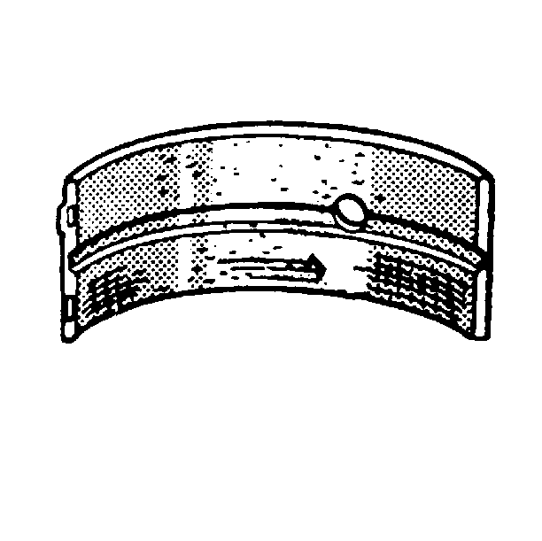
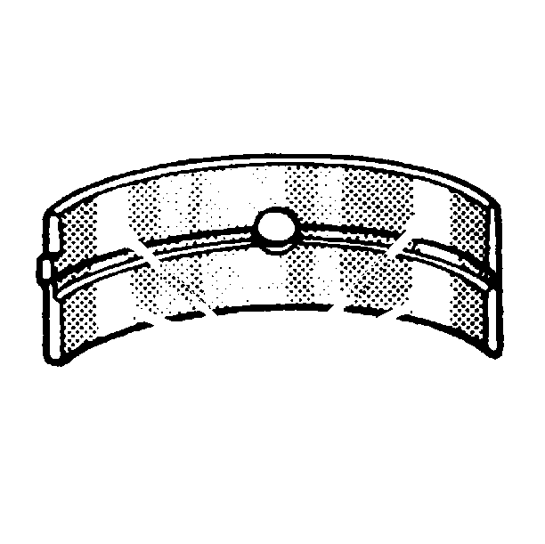
If the lower half of the bearing is worn or damaged, both upper and lower halves should be replaced.
Generally, if the lower half is suitable for use, the upper half should also be suitable for us.
Crankshaft and Bearing Cleaning and Inspection Inspection
Tool Required
J 7872 Magnetic Base Dial Indicator Set
- Remove the clutch pilot bearing.
- Clean the crankshaft with solvent.
- Thoroughly clean all oil passages and inspect for restrictions or burrs.
- Dry the crankshaft with compressed air.
- Perform a visual inspection of the crankshaft for damage.
- Inspect the crankshaft journals for wear (1).
- Inspect the crankshaft journals for grooves or scoring (2).
- Inspect the crankshaft journals for scratches or wear (3).
- Inspect the crankshaft journals for pitting or imbedded bearing material (4).
- Measure the crankshaft journals for out-of-round.
- Measure the crankshaft journals for taper.
- Measure the crankshaft runout.
- Use the J 7872 in order to measure the crankshaft runout at the front and rear intermediate journals.
- Use the J 7872 in order to measure the runout of the crankshaft rear flange.
- Install a new clutch pilot bearing.
- Inspect crankshaft bearings for craters or pockets. Flattened sections on the bearing halves also indicate fatigue.
- Inspect the crankshaft bearings for excessive scoring or discoloration.
- Inspect the crankshaft bearings for dirt or debris imbedded into the bearing material.
- Inspect the crankshaft bearings for improper seating indicated by bright, polished sections of the bearing.

Important: Use care when handling the crankshaft. Avoid damage to the bearing surfaces or the lobes of the crankshaft position reluctor ring. Damage to the teeth of the crankshaft position reluctor ring may effect OBD II system performance.

Caution: Wear safety glasses in order to avoid eye damage.
Important: Reluctor ring teeth should not have imperfections on the rising or falling edges.
Imperfections of the reluctor ring teeth may effect OBD II system performance.
Journals should be smooth with no signs of scoring, wear, or damage.


Using wooden V blocks, support the crankshaft on the front and rear journals.
| 14.1. | Compare the measurements to Engine Mechanical Specifications . |
| 14.2. | Replace or repair the crankshaft if the measurements are not within the specifications. |

A properly installed clutch pilot bearing will be installed until flush to the face of the crankshaft.


If the lower half of the bearing is worn or damaged, both upper and lower halves should be replaced.
Generally, if the lower half is suitable for use, the upper half should also be suitable for us.
