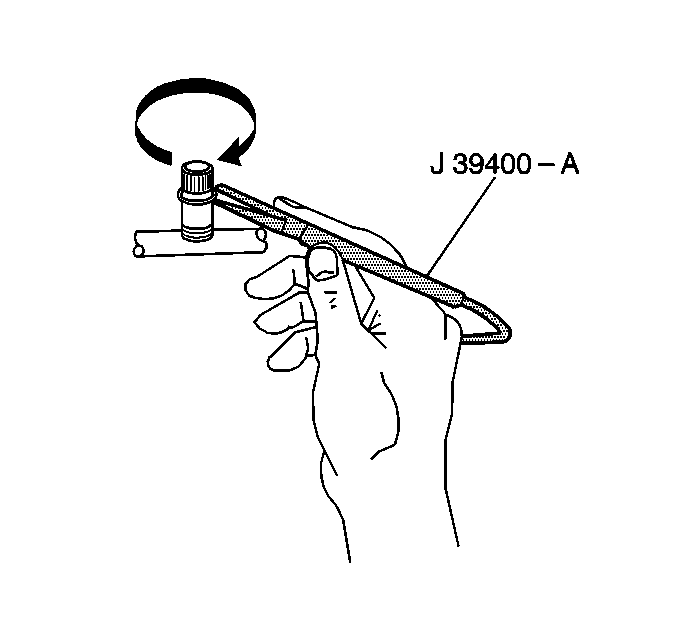
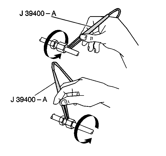
Caution: Do not operate the detector in a combustible atmosphere since its sensor operates at high temperature. Personal injury or damage to the equipment may result.
Caution: Take care to prevent personal injury which could occur due to touching a hot engine when testing. Tests should be done with the engine "Off" and as cool as possible. Do not operate the detector in a combustible atmosphere since its sensor operates at high temperature.
Perform a refrigerant leak test under the following conditions:
| • | Whenever you suspect a leak |
| • | After a service operation that disturbs the components, lines or connections |
There are several methods and special tools available for leak testing. Use care in all cases.
Electronic Leak Detector

Tools Required
J 39400 Electronic Leak Detector
Important: Electronic leak detectors are sensitive to the following liquids:
• Windshield washing solutions • Solvents • Cleaners • Adhesives
The J 39400 is useful for locating refrigerant leaks. The J 39400 operates on a 12 volt DC and emits signal that increases in frequency as R-134a is detected. Calibrate the instrument according to the included instructions. Ensure that the detector is properly calibrated for the type of refrigerant that you are testing. Place the GAS switch in the R-134a setting prior to testing.

Most leaks are found at the refrigerant fittings and connections. These leaks can be caused by the following conditions:
| • | Improper torque |
| • | Damaged O-rings |
| • | Lack of lubricant on the O-ring seals |
| • | Dirt or debris on the O-ring seals. |
| • | Lint from cotton gloves or shop cloths |
Important: Follow the refrigerant system around a continuous path so that no potential leaks are missed. Test all areas of the system in order to ensure the entire system is leak free, even if you have already found a leak.
Observe the scan rate and follow the manufacturer's instructions when using the electronic leak detector. Encircle each joint with the tip of the probe moving at 25-51 mm (1-2 in) per second. Ensure that the tip of the probe is no more than 6 mm (0.25 in) away from the surface without blocking the air intake. An audible tone that goes from 1-2 clicks per second to a solid alarm indicates a leak. Adjust the balance arm frequently in order to maintain the clicks.
Use this procedure in order to test the following components:
| • | The evaporator inlet and outlet |
| • | The accumulator inlet and outlet |
| • | All of the brazed and welded areas |
| • | Areas that show signs of damage |
| • | Hose couplings |
| • | The compressor rear head |
| • | Housing joints |
Service Ports/Access Valves
The sealing cap is the primary seal for the service ports. The cap contains a specially designed O-ring or gasket that provides a leak-free seal. The following conditions will result in a loss of refrigerant charge:
| • | A missing cap |
| • | A wrong cap |
Evaporator Core
Leaks in the evaporator core are the most difficult to find. Use the following procedure in order to test the core:
- Turn on the blower fan to HI for 15 seconds or longer.
- Turn off the blower fan.
- Wait 10 minutes.
- Remove the blower motor resistor.
- Insert the leak detector probe as close to the evaporator as possible.
- Use a flashlight in order to visually inspect the core face for evidence of refrigerant oil.
Refer to Blower Motor Resistor Replacement .
If the detector emits a solid alarm, a leak has been found.
Compressor Block Fitting and Shaft Seal
- Blow shop air behind the compressor/clutch pulley and in front of the compressor/clutch pulley for at least 15 seconds.
- Wait 1-2 minutes.
- Use the detector in order to probe the area in front of the pulley.
If the detector emits a solid alarm, a leak has been found.
