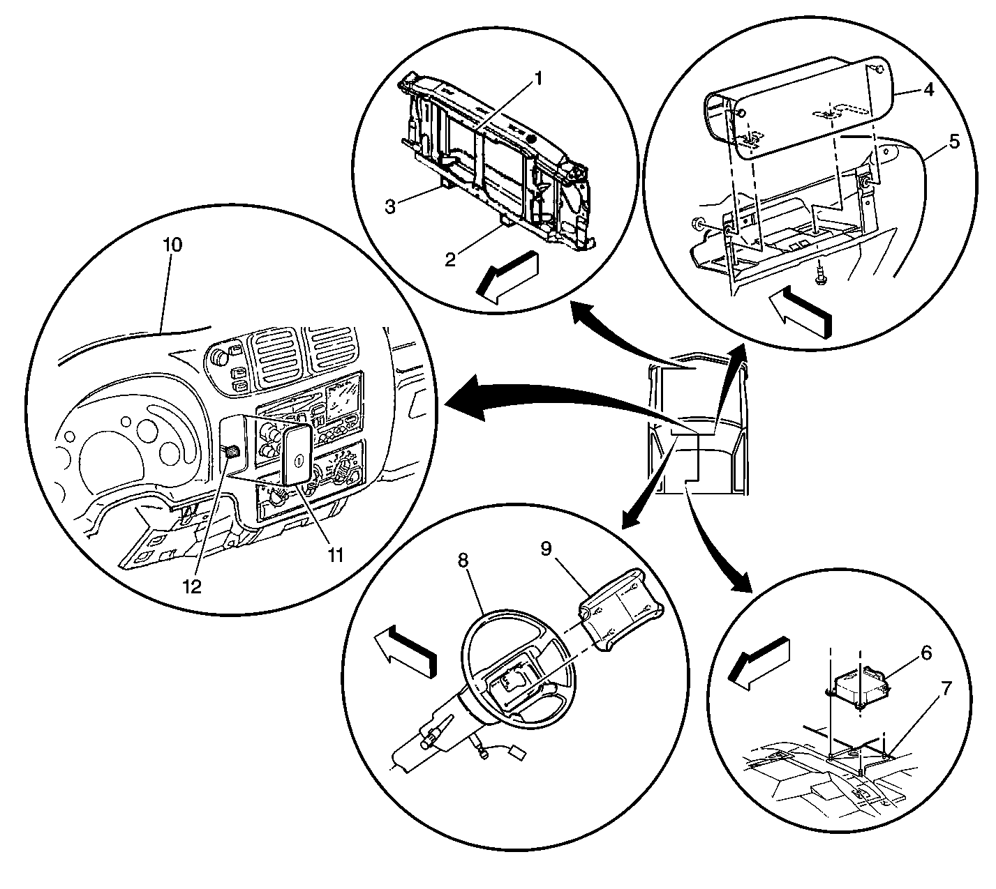
Name | Location | Locator View | Connector End View |
|---|---|---|---|
Data Link Connector | Lower LH side of instrument panel | -- | Electrical Diagnosis Connector End Views Page 202-3 |
GAUGES Fuse 4 (IP Fuse Block) | In the IP Fuse Block | IP Fuse Block Details in Power Distribution in Electrical Diagnosis | -- |
ILLUM Fuse 5 (IP Fuse Block) | In the IP Fuse Block | IP Fuse Block Details in Power Distribution in Electrical Diagnosis | -- |
Instrument Cluster | In the IP ahead of the steering column | -- | Electrical Diagnosis Connector End Views Page 202-10 |
IP Fuse Block | LH side of the IP near the left front side door jamb switch | Figure 8 in Electrical Component Location Views in Electrical Diagnosis | -- |
Seat Belt Switch | Under driver's seat | Figure 20 in Electrical Component Location Views in Electrical Diagnosis | -- |
SIR Fuse 16 (IP Fuse Block) | In the IP Fuse Block | IP Fuse Block Details in Power Distribution in Electrical Diagnosis | -- |
Supplemental Restraint Front End Discriminating Sensor, LH | On front frame cross-member, just inside the LH frame rail | -- | |
Supplemental Restraint Front End Discriminating Sensor, RH | On front frame cross-member, just inside the RH frame rail | -- | |
Supplemental Restraint IP Module Switch | On the instrument panel, to the left of the radio | -- | |
Supplemental Restraint IP Module | RH side of instrument panel | -- | |
Supplemental Restraint Sensing And Diagnostic Module | Between driver and passenger seat below the console and carpeting | -- | |
Supplemental Restraint Steering Wheel Module | In steering wheel | -- | |
Supplemental Restraint Steering Wheel Module Coil | In steering column | -- | -- |
Truck Body Control Module | Lower rear of IP on the heater assembly | Figure 8 in Electrical Component Location Views in Electrical Diagnosis | -- |
Truck Body Control Module Connector C2 (24 Cavities) | Lower rear of IP on the heater assembly | -- | Electrical Diagnosis Connector End Views Page 202-15 |
C109 (SRS Body harness to antilock brake 4WAL harness connector) (2 Cavities) | LH side of engine compartment, near the electronic brake control module) | -- | -- |
C200 (SRS IP Harness to Body Harness Connector) (2 Cavities) | RH side of dash, part of Connector C203 assembly | -- | -- |
C201 (Passenger Supplemental Restraint pigtail to IP Harness Connector) (2 Cavities) | Near Passenger Inflatable Restraint Module | -- | -- |
C203 (Body Harness to IP Harness) (116 Cavities) | RH side of dash | Figure 9 in Electrical Component Location Views in Electrical Diagnosis | Electrical Diagnosis Connector End Views Page 202-26 |
C207 (Seat Belt Switch Pigtail Connector, 2 Cavities) | Driver's Seat Belt Switch pigtail lead connector | -- | -- |
C214 (SRS Body harness to steering column harness) (2 Cavities) | Front of dash area, near steering column | -- | -- |
G118 (Circuit 1851, 4WAL/SIR Harness) | RH frame rail forward of RH front wheel | -- | -- |
G203 Circuit 1050, Body Harness) | RH Dash panel, between IP Body Connector C203 and Splice Packs | -- | -- |
S205 (Circuit 1220, IP Harness) | Between the breakouts for the radio and Truck Body Control Module Connector C3, 8 cm from the breakout to the radio | -- | -- |
S282 (Circuit 1382, IP Harness, W/ 4WD) | Between the breakouts to Truck Body Control Module Connector C3 and the radio, 6 cm from the breakout to the control module | -- | -- |
SP203 (Circuit 1050 Splice Pack, IP Harness) | On the IP Assembly, in front of the IP ashtray assembly | -- | -- |

