Tools Required
| • | J 33792 Side
Bearing Adjuster Socket |
| • | J 42213 Side
Bearing Adjuster Socket |

Notice: Use the correct fastener in the correct location. Replacement fasteners
must be the correct part number for that application. Fasteners requiring
replacement or fasteners requiring the use of thread locking compound or sealant
are identified in the service procedure. Do not use paints, lubricants, or
corrosion inhibitors on fasteners or fastener joint surfaces unless specified.
These coatings affect fastener torque and joint clamping force and may damage
the fastener. Use the correct tightening sequence and specifications when
installing fasteners in order to avoid damage to parts and systems.
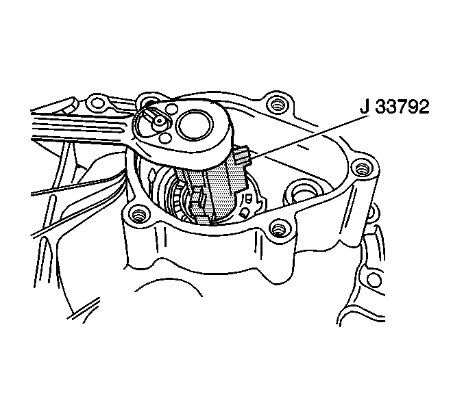
- Tighten the right
sleeve using the J 33792
.
Tighten
Tighten the right sleeve to 140 N·m (103 lb ft).

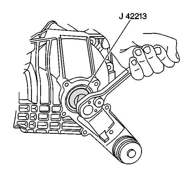
- Tighten the left sleeve using the J 42213
Tighten
Tighten the left sleeve to 140 N·m (103 lb ft).

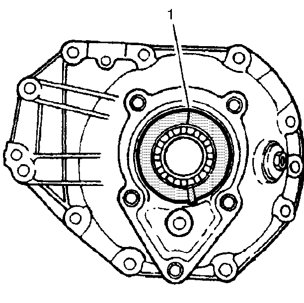
- Mark the location of the
adjusting sleeves in relation to the carrier halves (1), in order to count
the notches in the adjusting sleeves when turned.
- Turn the right adjusting sleeve out two notches using the J 33792
.
- Turn the left adjusting sleeve in one notch using the J 42213
.
- Rotate the pinion several times in order to seat the bearings.

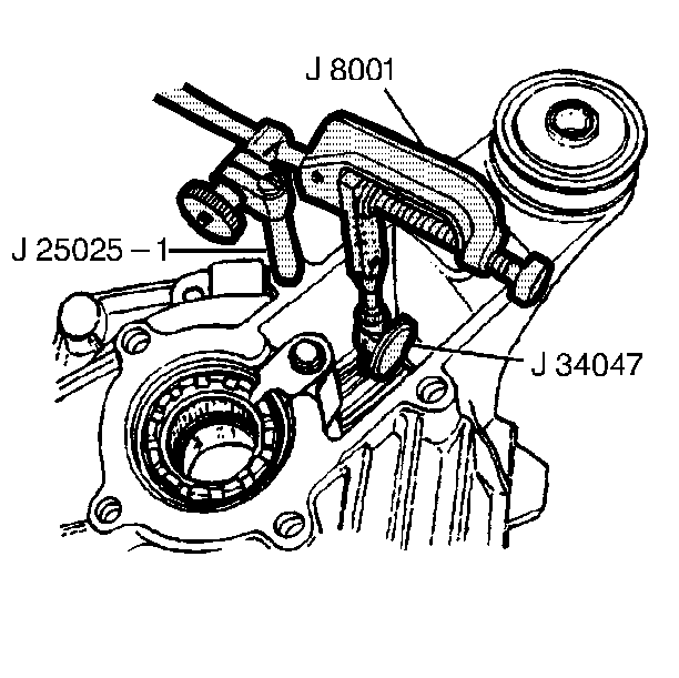
- Install the J 34047
, the J 25025-1
, and the J 8001
.
- Place the indicator stem at the heel end of a tooth.
- Move the case through the case's free play while holding the pinion
flange. Record the dial indicator reading.
- Divide the dial indicator reading by two in order to obtain the
actual backlash. For example, a dial indicator reading of 0.16 mm (0.006 in)
means that there is actually 0.08 mm (0.003 in) backlash.
- Inspect and record the backlash at three or four points around
the ring gear.
| • | Hold the pinion stationary when checking backlash. |
| • | If the backlash varies more than 0.05 mm (0.002 in),
check for the following conditions: |
| - | A distorted case flange |
| - | Uneven bolting conditions |
| - | Foreign matter between the case and the ring gear |
| • | Gear backlash should be between 0.08-0.25 mm (0.003-0.010 in)
with a preferred specification of 0.13-0.18 mm (0.005-0.007 in). |
| • | If the backlash is incorrect, adjust the sleeves as necessary.
Maintain one notch preload on the side bearings. For example, if the right
sleeve needs to be turned out one notch, turn in the left sleeve one
notch. |
| • | In order to increase backlash, turn the left sleeve in and turn
the right sleeve out the same amount. In order to decrease backlash, turn
the right sleeve in and turn the left sleeve out the same amount. |
- When the backlash is correct, mark the position of the sleeves
in order to keep the sleeves in the same location.


