Differential Carrier Overhaul Except Bravada
Disassembly Procedure
Tools Required
| • | J 8107-2 Differential
Side Bearing Remover |
| • | J 21551 Output
Shaft Bearing Remover |
| • | J 33791 Bushing
Remover and Installer Set |
| • | J 33792 Side
Bearing Adjuster Socket |
| • | J 33837 Pinion
Bearing Cup Remover and Installer |
| • | J 36611 Output
Shaft Bearing Remover |
| • | J 42213 Side
Bearing Adjuster Socket |
- Remove the bolts, the shift cable housing, and the spring.
- Remove the tube and the thrust washer.
- Remove the spring and shift shaft with fork.
- Remove the axle shaft.
- Remove the clutch gear with the retaining ring.
- Remove the right inner axle shaft to housing seal using a suitable
seal remover.
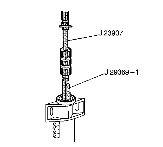
- Remove the right inner
axle shaft bearing using the J 29369-1
and the J 23907
.
- Remove the thrust washer.
- Remove the clutch sleeve and shaft.
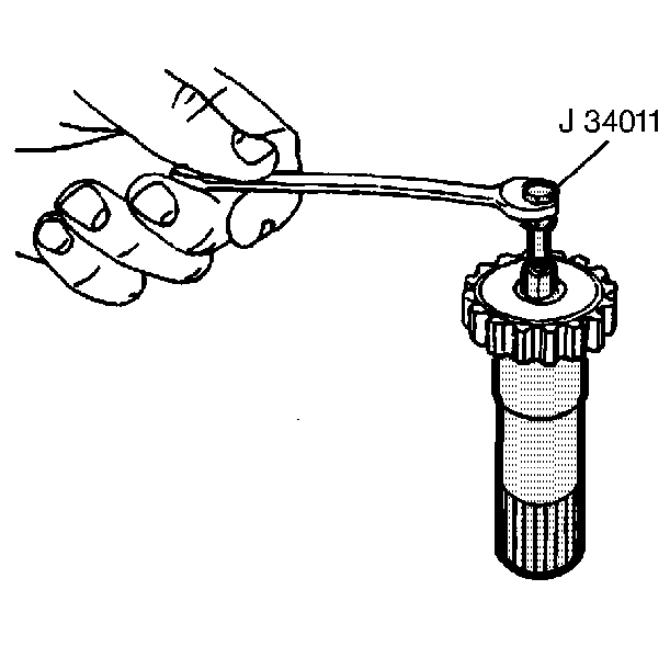
- Remove the pilot bearing
from the clutch shaft using the J 34011
.
- Remove the washer.
- Remove the left side carrier cover bolts.
- Remove the left side cover and seal assembly.
- Remove the carrier halves assembly bolts.
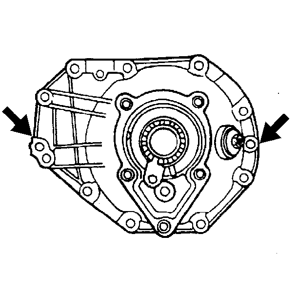
- Separate the carrier.
Insert a screwdriver into the slots provided and pry in order to separate
the carrier.
- Remove the differential case assembly.
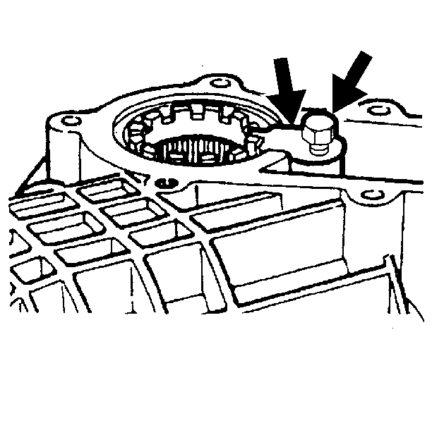
- Remove the bolts and lock
tabs from the side bearing adjuster sleeves.
- Remove the bearing cups and sleeves from the carrier.
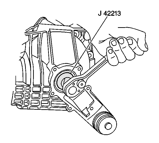
- Turn the left sleeve until the cup is pushed out of the carrier using
the J 42213
.
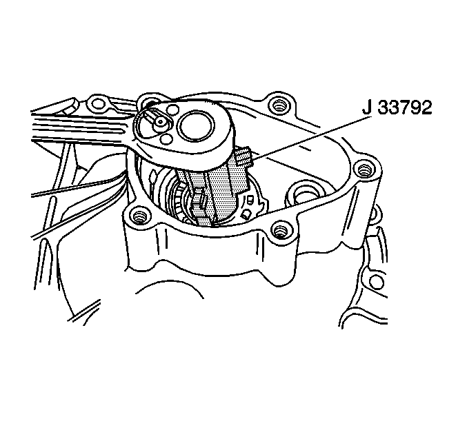
- Turn the right sleeve until the cup is pushed out of the carrier using
the J 33792
.
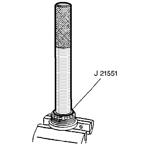
- Remove the bearing from
the right adjuster sleeve using the J 21551
.
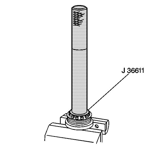
- Remove the bearing from the left adjuster sleeve using the J 36611
.
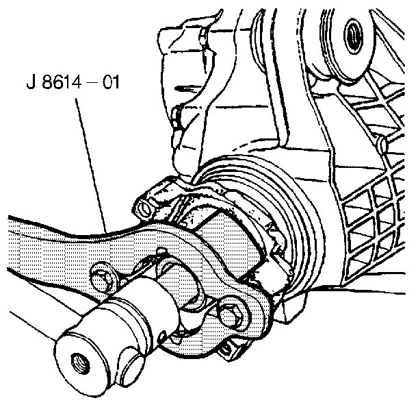
- Remove the pinion yoke
nut and washer using the J 8614-01
.
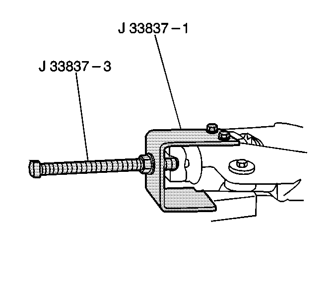
- Mount the left carrier
case half and drive the pinion out of the carrier using the J 33837
-1 and the J 33837-3.
- Remove the pinion yoke and the deflector.
- Remove the pinion with the spacer and the pinion bearing and shim.
- Remove the spacer from the pinion.
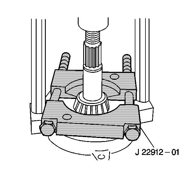
- Remove the bearing from
the pinion using a press and the J 22912-B
.
- Remove the shim.
- Remove the outer pinion bearing, the seal and the cup using the J 33837
-1, the J 33837-3
and the J 33837-6.
| 30.1. | Insert the J 33837-6 into the pinion bore. |
| 30.2. | Thread the forcing screw (J 33837-3) into the J 33837-6. |
| 30.3. | In order to pull the parts from the case, turn the forcing screw. |
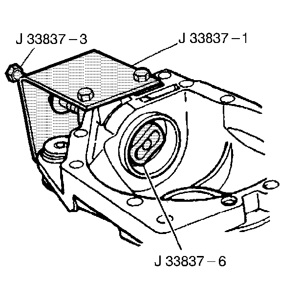
- Remove the inner bearing
cup by pushing out using the J 33837
-1, the J 33837-3 and the J 33837-6.
- Remove the differential pinion bolt and shaft from the differential
case.
- Remove the differential pinion gears and the thrust washers.
- Remove the side gears and the thrust washers. Mark the side gears
and case for reinstallation in the original location.
- Remove the ring gear mounting bolts.
- Remove the ring gear. Drive the gear off using a brass drift and
hammer. Do not pry between the ring gear and the case.
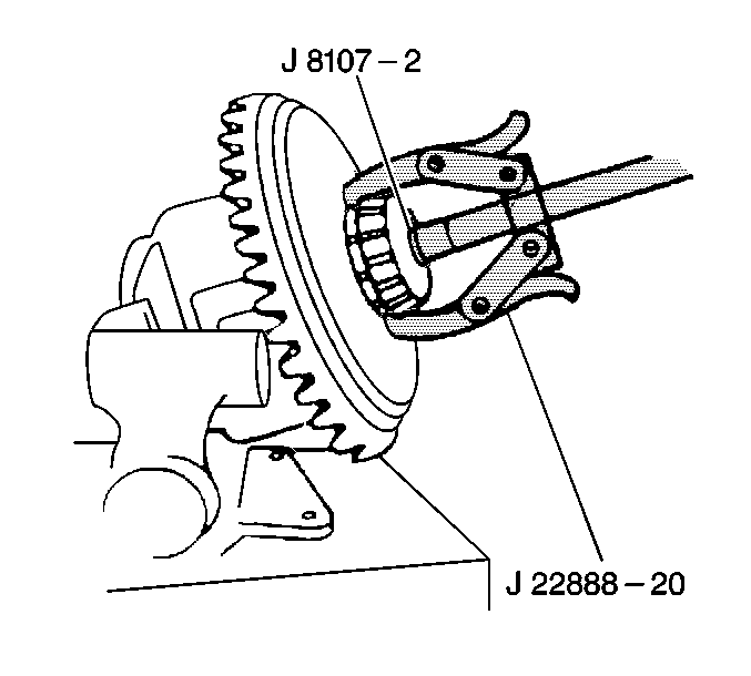
- Remove the side bearings using the J 22888-20A
and the J 8107-2
.
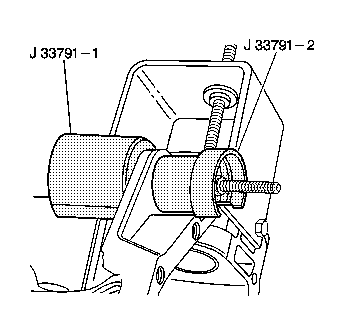
- Remove the case bushing
using the J 33791
-1 and
the J 33791-2.


