GM Service Manual Online
For 1990-2009 cars only

Name

Location

Locator View

Connector End View

1-2 Shift Solenoid (1-2 SS) Valve

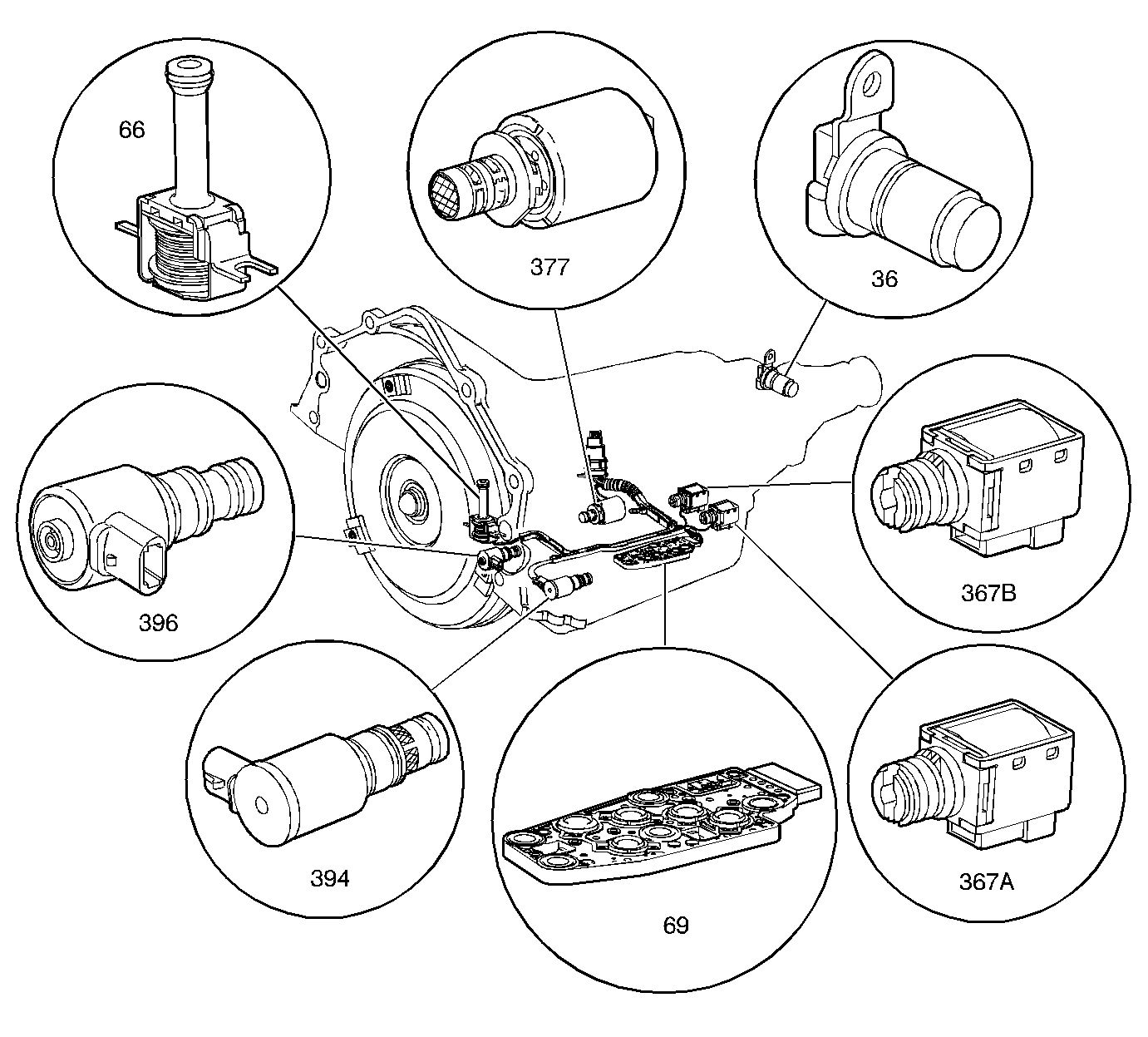
Inside the automatic transmission


Object Number: 62792  Size: LF

(36)Vehicle Speed Sensor
(66)Torque Converter Clutch Solenoid Valve
(69)Automatic Transmission Fluid Pressure Manual Valve Position Switch
(367a)1-2 Shift Solenoid Valve
(367b)2-3 Shift Solenoid Valve
(377)Pressure Control Solenoid Valve
(394)3-2 Shift Solenoid Valve Assembly
(396)Torque Converter Clutch Pulse Width Modulation Solenoid Valve
in Automatic Transmission - 4L60E in Transmission/ Transaxle

Automatic Transmission Internal Connector End Views in Automatic Transmission - 4L60E in Transmission/ Transaxle

2-3 Shift Solenoid (2-3 SS) Valve

Inside the automatic transmission


Object Number: 62792  Size: LF

(36)Vehicle Speed Sensor
(66)Torque Converter Clutch Solenoid Valve
(69)Automatic Transmission Fluid Pressure Manual Valve Position Switch
(367a)1-2 Shift Solenoid Valve
(367b)2-3 Shift Solenoid Valve
(377)Pressure Control Solenoid Valve
(394)3-2 Shift Solenoid Valve Assembly
(396)Torque Converter Clutch Pulse Width Modulation Solenoid Valve
in Automatic Transmission - 4L60E in Transmission/ Transaxle

Automatic Transmission Internal Connector End Views in Automatic Transmission - 4L60E in Transmission/ Transaxle

3-2 Shift Solenoid (3-2 SS) Valve Assembly

Inside the automatic transmission


Object Number: 62792  Size: LF

(36)Vehicle Speed Sensor
(66)Torque Converter Clutch Solenoid Valve
(69)Automatic Transmission Fluid Pressure Manual Valve Position Switch
(367a)1-2 Shift Solenoid Valve
(367b)2-3 Shift Solenoid Valve
(377)Pressure Control Solenoid Valve
(394)3-2 Shift Solenoid Valve Assembly
(396)Torque Converter Clutch Pulse Width Modulation Solenoid Valve
in Automatic Transmission - 4L60E in Transmission/ Transaxle

Automatic Transmission Internal Connector End Views in Automatic Transmission - 4L60E in Transmission/ Transaxle

4WD Fuse 15 (IP Fuse Block) (4.3L Engine)

In the IP Fuse Block

IP Fuse Block Details in Power Distribution in Electrical Diagnosis

--

A/C Compressor (4.3L Engine)

Top LH front of engine

--

Electrical Diagnosis Connector End Views Page 202-0

A/C Compressor Clutch

Part of A/C Compressor

--

--

A/C Compressor Clutch Diode (4.3 L Engine)

In engine harness breakout, 7.5 cm from the breakout to the A/C Compressor and high pressure switch

--

--

A/C Compressor Clutch Relay (4.3L Engine)

In the Underhood Bussed Electrical Center

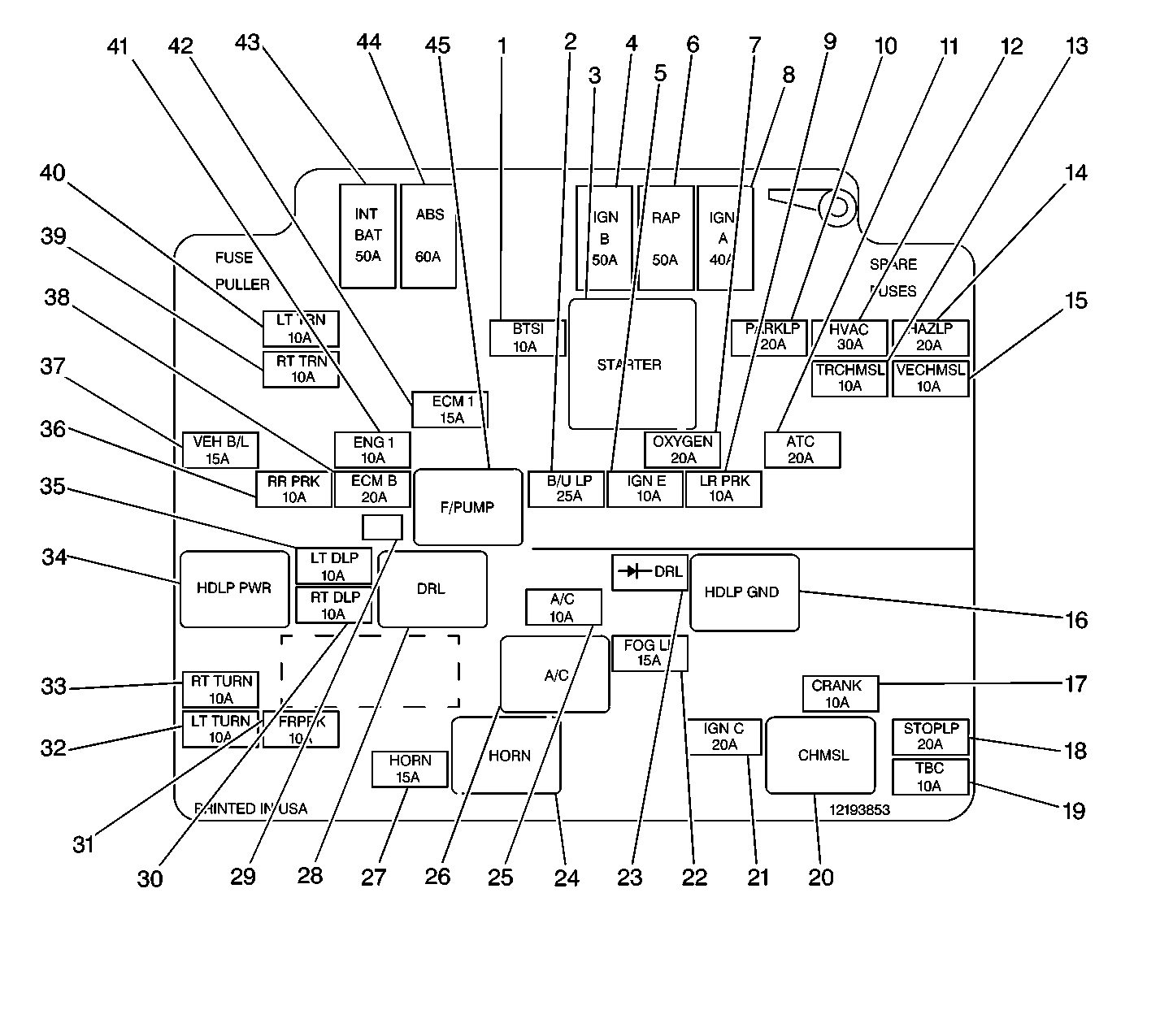
Figure 6: UBEC Internal Location View


Object Number: 212233  Size: LF
(1)BTSI Fuse (10 A) (W/ A/T)
(2)B/U LP Fuse (UBEC) (25 A)
(3)Starter Relay (Mini Relay)
(4)IGN B MaxiFuse (50 A)
(5)IGN E Fuse (UBEC) (10 A)
(6)RAP MaxiFuse (40 A)
(7)OXYSEN Fuse (UBEC) (20 A)
(8)IGN A MaxiFuse (UBEC) (40 A)
(9)LR PRK (10 A)
(10)PARKLP Fuse (20 A)
(11)ATC Fuse (20 A)
(12)HVAC Fuse (30 A)
(13)TRCHMSL Fuse (10 A)
(14)HAZLP Fuse (20 A)
(15)VECHMSL Fuse (10 A)
(16)Headlamp Grounding Relay (Micro Relay)
(17)CRANK Fuse (10 A)
(18)STOPLP Fuse (20 A)
(19)TBC Fuse (10 A)
(20)High Mounted Stop Lamp Relay (Micro Relay) (Pickup)
(21)IGN C Fuse (15 A)
(22)FOG LP Fuse (15 A)
(23)Daytime Running Lights Relay Diode
(24) A/C Fuse (10 A)
(25)A/C Compressor Clutch Relay (Micro Relay)
(26)Horn Relay (Micro Relay)
(27)HORN Fuse (15 A)
(28)Daytime Running Lights Relay (Micro Relay)
(29)Fuel Pump Prime Connector
(30)RT HDLP Fuse (10 A)
(31)FR PRK Fuse (10 A)
(32)LT TURN Fuse (Front) (10 A)
(33)RT TURN Fuse (Front) (10 A)
(34)Headlamp Power Relay (Micro Relay)
(35)LT HDLP Fuse (10 A)
(36)RR PRK Fuse (10 A)
(37)VEH B/U Fuse (15 A)
(38)ECM B Fuse (20 A)
(39)RT TRN Fuse (Rear) (10 A)
(40)LT TRN Fuse (Rear) (10 A)
(41)ENG I Fuse (UBEC) (10 A)
(42)ECM I Fuse (UBEC) (15 A)
(43)INT BAT MaxiFuse (50 A)
(44)ABS MaxiFuse (60 A)
(45)Fuel Pump Relay (Micro Relay)
in Starter And Charging Component Views in Engine Electrical in Engine

--

A/C Compressor High Pressure Switch (4.3L Engine)

Rear of A/C Compressor

--

--

A/C Compressor Pressure Cycling Switch (4.3L Engine)

At the Accumulator

--

Electrical Diagnosis Connector End Views Page 202-0

A/C Fuse (UBEC)

In the Underhood Bussed Electrical Center

Figure 6: UBEC Internal Location View


Object Number: 212233  Size: LF
(1)BTSI Fuse (10 A) (W/ A/T)
(2)B/U LP Fuse (UBEC) (25 A)
(3)Starter Relay (Mini Relay)
(4)IGN B MaxiFuse (50 A)
(5)IGN E Fuse (UBEC) (10 A)
(6)RAP MaxiFuse (40 A)
(7)OXYSEN Fuse (UBEC) (20 A)
(8)IGN A MaxiFuse (UBEC) (40 A)
(9)LR PRK (10 A)
(10)PARKLP Fuse (20 A)
(11)ATC Fuse (20 A)
(12)HVAC Fuse (30 A)
(13)TRCHMSL Fuse (10 A)
(14)HAZLP Fuse (20 A)
(15)VECHMSL Fuse (10 A)
(16)Headlamp Grounding Relay (Micro Relay)
(17)CRANK Fuse (10 A)
(18)STOPLP Fuse (20 A)
(19)TBC Fuse (10 A)
(20)High Mounted Stop Lamp Relay (Micro Relay) (Pickup)
(21)IGN C Fuse (15 A)
(22)FOG LP Fuse (15 A)
(23)Daytime Running Lights Relay Diode
(24) A/C Fuse (10 A)
(25)A/C Compressor Clutch Relay (Micro Relay)
(26)Horn Relay (Micro Relay)
(27)HORN Fuse (15 A)
(28)Daytime Running Lights Relay (Micro Relay)
(29)Fuel Pump Prime Connector
(30)RT HDLP Fuse (10 A)
(31)FR PRK Fuse (10 A)
(32)LT TURN Fuse (Front) (10 A)
(33)RT TURN Fuse (Front) (10 A)
(34)Headlamp Power Relay (Micro Relay)
(35)LT HDLP Fuse (10 A)
(36)RR PRK Fuse (10 A)
(37)VEH B/U Fuse (15 A)
(38)ECM B Fuse (20 A)
(39)RT TRN Fuse (Rear) (10 A)
(40)LT TRN Fuse (Rear) (10 A)
(41)ENG I Fuse (UBEC) (10 A)
(42)ECM I Fuse (UBEC) (15 A)
(43)INT BAT MaxiFuse (50 A)
(44)ABS MaxiFuse (60 A)
(45)Fuel Pump Relay (Micro Relay)
in Starter And Charging Component Views in Engine Electrical in Engine

--

ABS Fuse 22 (IP Fuse Block)

In the IP Fuse Block

IP Fuse Block Details in Power Distribution in Electrical Diagnosis

--

AM/FM Stereo Radio

Center of the Instrument Panel

Figure 9 in Electrical Component Location Views in Electrical Diagnosis

--

AM/FM Stereo Radio Connector C2 (10 Cavities)

LH rear of radio

--

Electrical Diagnosis Connector End Views Page 202-2

Automatic Transmission (4.3 L Engine)

See In-Line Connector C175 (4.3L Engine)

--

--

Automatic Transmission Fluid Pressure (TFP) Manual Valve Position Switch

Inside the automatic transmission


Object Number: 62792  Size: LF

(36)Vehicle Speed Sensor
(66)Torque Converter Clutch Solenoid Valve
(69)Automatic Transmission Fluid Pressure Manual Valve Position Switch
(367a)1-2 Shift Solenoid Valve
(367b)2-3 Shift Solenoid Valve
(377)Pressure Control Solenoid Valve
(394)3-2 Shift Solenoid Valve Assembly
(396)Torque Converter Clutch Pulse Width Modulation Solenoid Valve
in Automatic Transmission - 4L60E in Transmission/ Transaxle

Automatic Transmission Internal Connector End Views in Automatic Transmission - 4L60E in Transmission/ Transaxle

Body Bussed Electrical Center (BBEC)

LH side of dash, near IP fuse Block

--

--

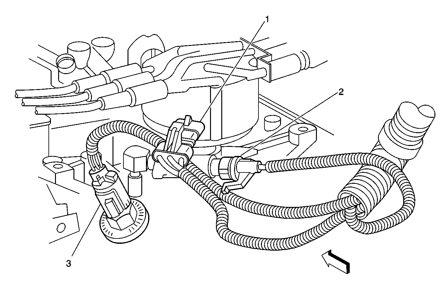
Camshaft Position Sensor (4.3L Engine)

Rear of Distributor

Camshaft Position (CMP) sensor, Knock Sensor (KS), and Fuel Pump/Oil Pressure Switch

Object Number: 212680  Size: MF
(1)Camshaft Position (CMP) sensor
(2)Fuel Pump/Oil Pressure Switch
(3)Knock Sensor (KS)
in Engine Controls Component Views in Engine Controls - 4.3L in Engine

--

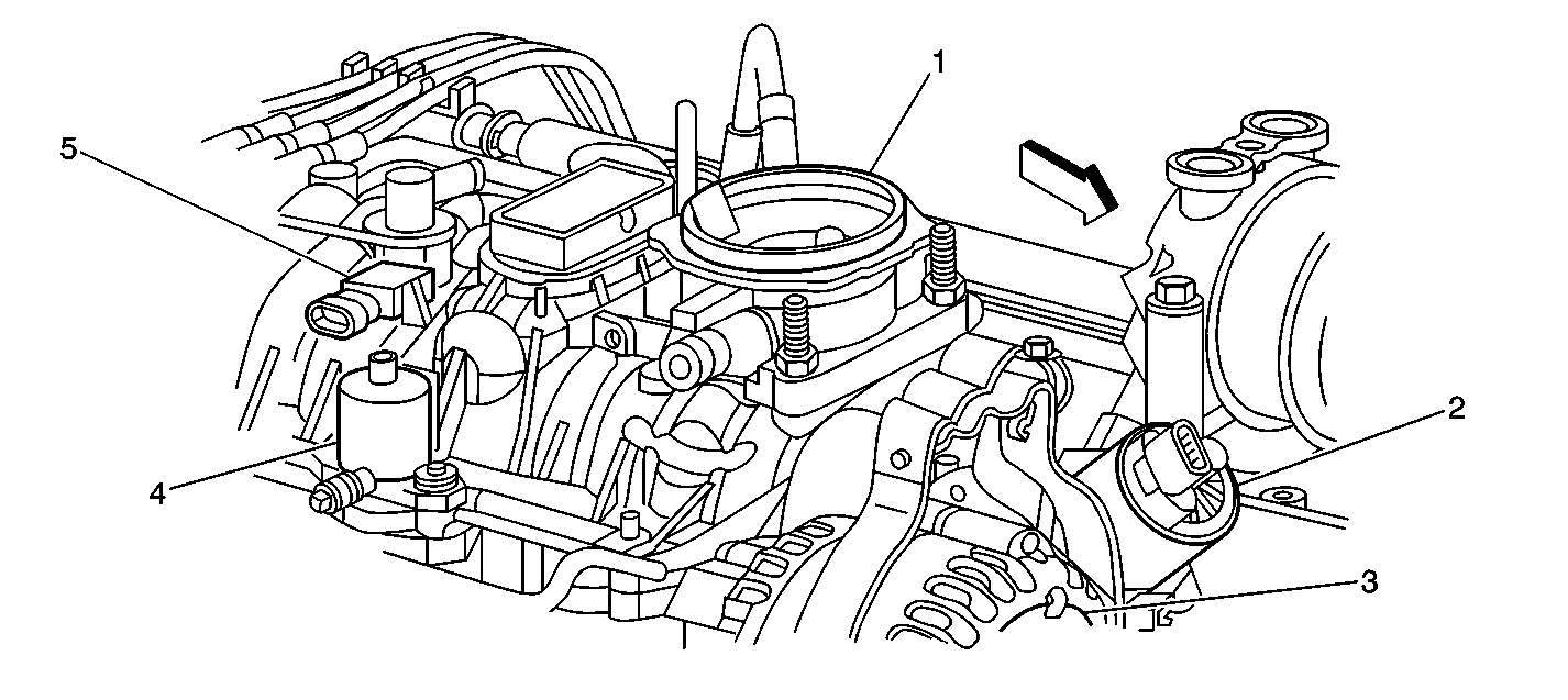
Central Sequential Fuel Injection (CSFI)

Top center of engine, forward of distributor

MAP, EGR, Purge Solenoid, and Throttle Body

Object Number: 209643  Size: SF
(1)Throttle Body
(2)Exhaust Gas Recirculation (EGR) Valve
(3)Generator
(4)Evaporative Emission (EVAP) Canister Purge Valve
(5)Manifold Absolute Pressure (MAP) Sensor
in Engine Controls Component Views in Engine Controls - 4.3L in Engine

--

CIGAR LTR Fuse 2 (IP Fuse Block)

In the IP Fuse Block

IP Fuse Block Details in Power Distribution in Electrical Diagnosis

--

CLSTR Fuse 11 (IP Fuse Block)

In the IP Fuse Block

IP Fuse Block Details in Power Distribution in Electrical Diagnosis

--

Crankshaft Position Sensor (4.3L Engine)

Below RH front of engine near harmonic balancer

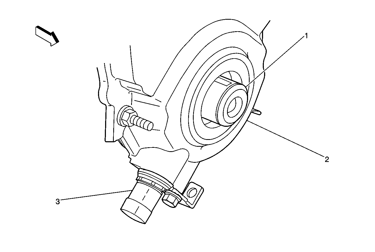
Crankshaft Position (CKP) Sensor


Object Number: 235188  Size: MF
(1)Crankshaft
(2)Front Engine Cover
(3)Crankshaft Position (CKP) Sensor
in Engine Controls Component Views in Engine Controls - 4.3L in Engine

--

Cruise Control Module

LH rear of engine compartment on cowl

--

--

Data Link Connector

Lower LH side of instrument panel

--

Electrical Diagnosis Connector End Views Page 202-3

Distributor (4.3L Engine)

Top rear of engine

--

--

ECM B Fuse (UBEC)

In the Underhood Bussed Electrical Center

Figure 6: UBEC Internal Location View


Object Number: 212233  Size: LF
(1)BTSI Fuse (10 A) (W/ A/T)
(2)B/U LP Fuse (UBEC) (25 A)
(3)Starter Relay (Mini Relay)
(4)IGN B MaxiFuse (50 A)
(5)IGN E Fuse (UBEC) (10 A)
(6)RAP MaxiFuse (40 A)
(7)OXYSEN Fuse (UBEC) (20 A)
(8)IGN A MaxiFuse (UBEC) (40 A)
(9)LR PRK (10 A)
(10)PARKLP Fuse (20 A)
(11)ATC Fuse (20 A)
(12)HVAC Fuse (30 A)
(13)TRCHMSL Fuse (10 A)
(14)HAZLP Fuse (20 A)
(15)VECHMSL Fuse (10 A)
(16)Headlamp Grounding Relay (Micro Relay)
(17)CRANK Fuse (10 A)
(18)STOPLP Fuse (20 A)
(19)TBC Fuse (10 A)
(20)High Mounted Stop Lamp Relay (Micro Relay) (Pickup)
(21)IGN C Fuse (15 A)
(22)FOG LP Fuse (15 A)
(23)Daytime Running Lights Relay Diode
(24) A/C Fuse (10 A)
(25)A/C Compressor Clutch Relay (Micro Relay)
(26)Horn Relay (Micro Relay)
(27)HORN Fuse (15 A)
(28)Daytime Running Lights Relay (Micro Relay)
(29)Fuel Pump Prime Connector
(30)RT HDLP Fuse (10 A)
(31)FR PRK Fuse (10 A)
(32)LT TURN Fuse (Front) (10 A)
(33)RT TURN Fuse (Front) (10 A)
(34)Headlamp Power Relay (Micro Relay)
(35)LT HDLP Fuse (10 A)
(36)RR PRK Fuse (10 A)
(37)VEH B/U Fuse (15 A)
(38)ECM B Fuse (20 A)
(39)RT TRN Fuse (Rear) (10 A)
(40)LT TRN Fuse (Rear) (10 A)
(41)ENG I Fuse (UBEC) (10 A)
(42)ECM I Fuse (UBEC) (15 A)
(43)INT BAT MaxiFuse (50 A)
(44)ABS MaxiFuse (60 A)
(45)Fuel Pump Relay (Micro Relay)
in Starter And Charging Component Views in Engine Electrical in Engine

--

ECM I Fuse (UBEC)

In the Underhood Bussed Electrical Center

Figure 6: UBEC Internal Location View


Object Number: 212233  Size: LF
(1)BTSI Fuse (10 A) (W/ A/T)
(2)B/U LP Fuse (UBEC) (25 A)
(3)Starter Relay (Mini Relay)
(4)IGN B MaxiFuse (50 A)
(5)IGN E Fuse (UBEC) (10 A)
(6)RAP MaxiFuse (40 A)
(7)OXYSEN Fuse (UBEC) (20 A)
(8)IGN A MaxiFuse (UBEC) (40 A)
(9)LR PRK (10 A)
(10)PARKLP Fuse (20 A)
(11)ATC Fuse (20 A)
(12)HVAC Fuse (30 A)
(13)TRCHMSL Fuse (10 A)
(14)HAZLP Fuse (20 A)
(15)VECHMSL Fuse (10 A)
(16)Headlamp Grounding Relay (Micro Relay)
(17)CRANK Fuse (10 A)
(18)STOPLP Fuse (20 A)
(19)TBC Fuse (10 A)
(20)High Mounted Stop Lamp Relay (Micro Relay) (Pickup)
(21)IGN C Fuse (15 A)
(22)FOG LP Fuse (15 A)
(23)Daytime Running Lights Relay Diode
(24) A/C Fuse (10 A)
(25)A/C Compressor Clutch Relay (Micro Relay)
(26)Horn Relay (Micro Relay)
(27)HORN Fuse (15 A)
(28)Daytime Running Lights Relay (Micro Relay)
(29)Fuel Pump Prime Connector
(30)RT HDLP Fuse (10 A)
(31)FR PRK Fuse (10 A)
(32)LT TURN Fuse (Front) (10 A)
(33)RT TURN Fuse (Front) (10 A)
(34)Headlamp Power Relay (Micro Relay)
(35)LT HDLP Fuse (10 A)
(36)RR PRK Fuse (10 A)
(37)VEH B/U Fuse (15 A)
(38)ECM B Fuse (20 A)
(39)RT TRN Fuse (Rear) (10 A)
(40)LT TRN Fuse (Rear) (10 A)
(41)ENG I Fuse (UBEC) (10 A)
(42)ECM I Fuse (UBEC) (15 A)
(43)INT BAT MaxiFuse (50 A)
(44)ABS MaxiFuse (60 A)
(45)Fuel Pump Relay (Micro Relay)
in Starter And Charging Component Views in Engine Electrical in Engine

--

Electric Shift Transfer Case (W/ S4WD)

To the rear of the transmission

Figure 1: Electric Shift Transfer Case Locator View
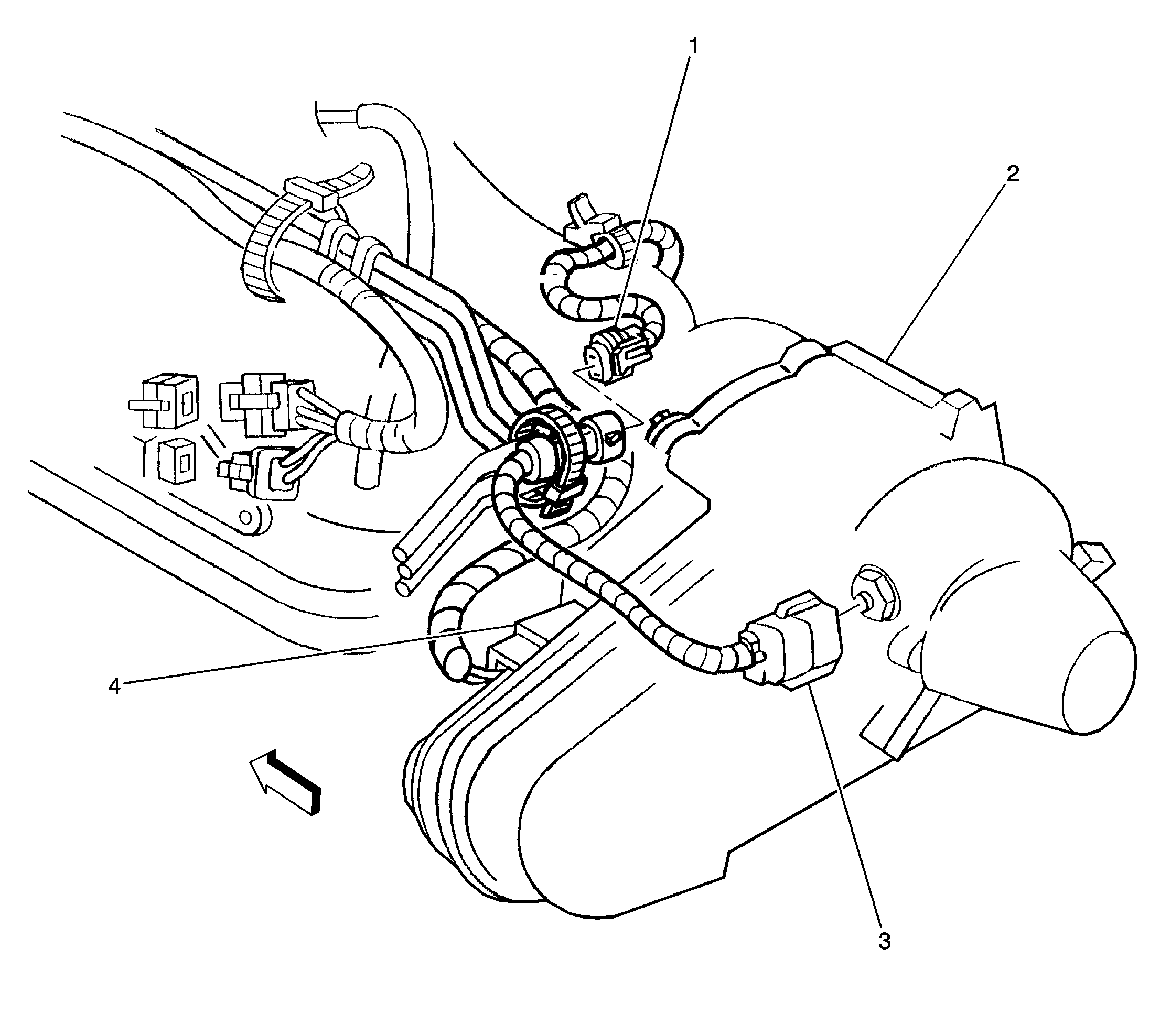

Object Number: 203300  Size: LF
(1)Connector C116 (Engine Harness to VSS Extension Harness)
(2)Electric Shift Transfer Case
(3)Vehicle Speed Sensor (W/ Electric Shift 4WD)
(4)Electric Shift Transfer Case extension harness connector
in Transfer Case Component Views in Transfer Case in Driveline/ Axle

--

Electronic Brake Control Module (Part of Brake Pressure Modulator Valve)

LH front fenderwell between the Underhood Bussed Electrical Center and Grommet P100

Figure 3: Brake Control Module Locator View
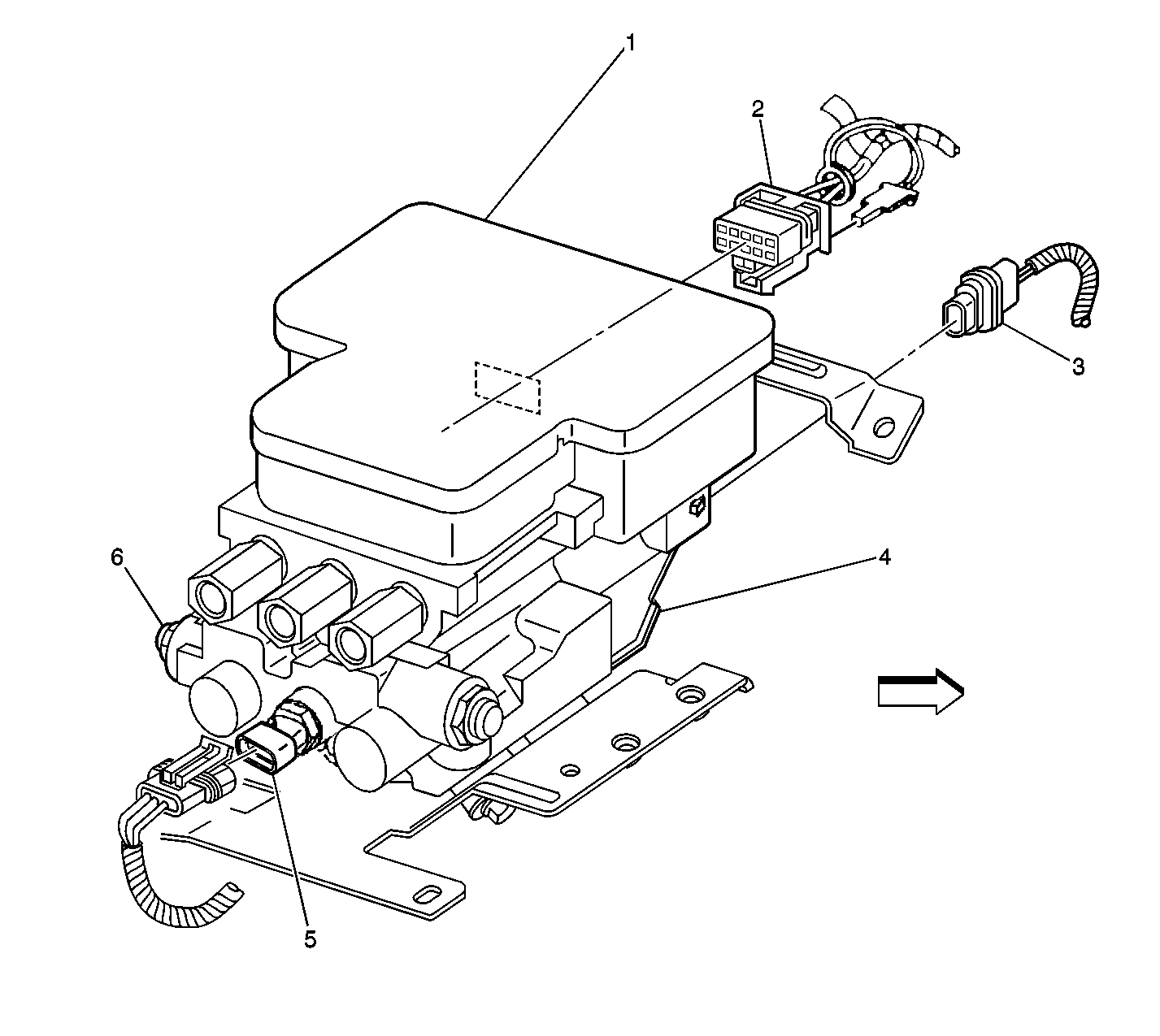

Object Number: 203299  Size: LF
(1)Electronic Brake Control Module
(2)Electronic Brake Control Module Connector C1
(3)Electronic Brake Control Module Connector C3
(4)Brake Pressure Modulating Valve
(5)Brake Pressure Warning Switch
(6)Combination Valve
in Antilock Brakes System Component Views in Antilock Brakes System in Brakes

--

Electronic Brake Control Module (Part of Brake Pressure Modulator Valve) Connector C1 (10 Cavities)

Body harness connector on LH of Electronic Brake Control Module/Brake Pressure Modulator Valve

Figure 3: Brake Control Module Locator View


Object Number: 203299  Size: LF
(1)Electronic Brake Control Module
(2)Electronic Brake Control Module Connector C1
(3)Electronic Brake Control Module Connector C3
(4)Brake Pressure Modulating Valve
(5)Brake Pressure Warning Switch
(6)Combination Valve
in Antilock Brakes System Component Views in Antilock Brakes System in Brakes

Antilock Brake System Connector End Views in Antilock Brake System in Brakes

Electronic Brake Control Module (Part of Brake Pressure Modulator Valve) Connector C2 (2 Cavities)

Body harness connector on LH of Electronic Brake Control Module/Brake Pressure Modulator Valve

Figure 3: Brake Control Module Locator View


Object Number: 203299  Size: LF
(1)Electronic Brake Control Module
(2)Electronic Brake Control Module Connector C1
(3)Electronic Brake Control Module Connector C3
(4)Brake Pressure Modulating Valve
(5)Brake Pressure Warning Switch
(6)Combination Valve
in Antilock Brakes System Component Views in Antilock Brakes System in Brakes

Antilock Brake System Connector End Views in Antilock Brake System in Brakes

Electronic Ignition Control Module (Part of Ignition Coil Assembly) (4.3L Engine)

Top RH side of engine

Ignition Coil, Ignition Control (IC) Module, MAP, Throttle Body, and Evaporative (EVAP) Canister Purge Valve
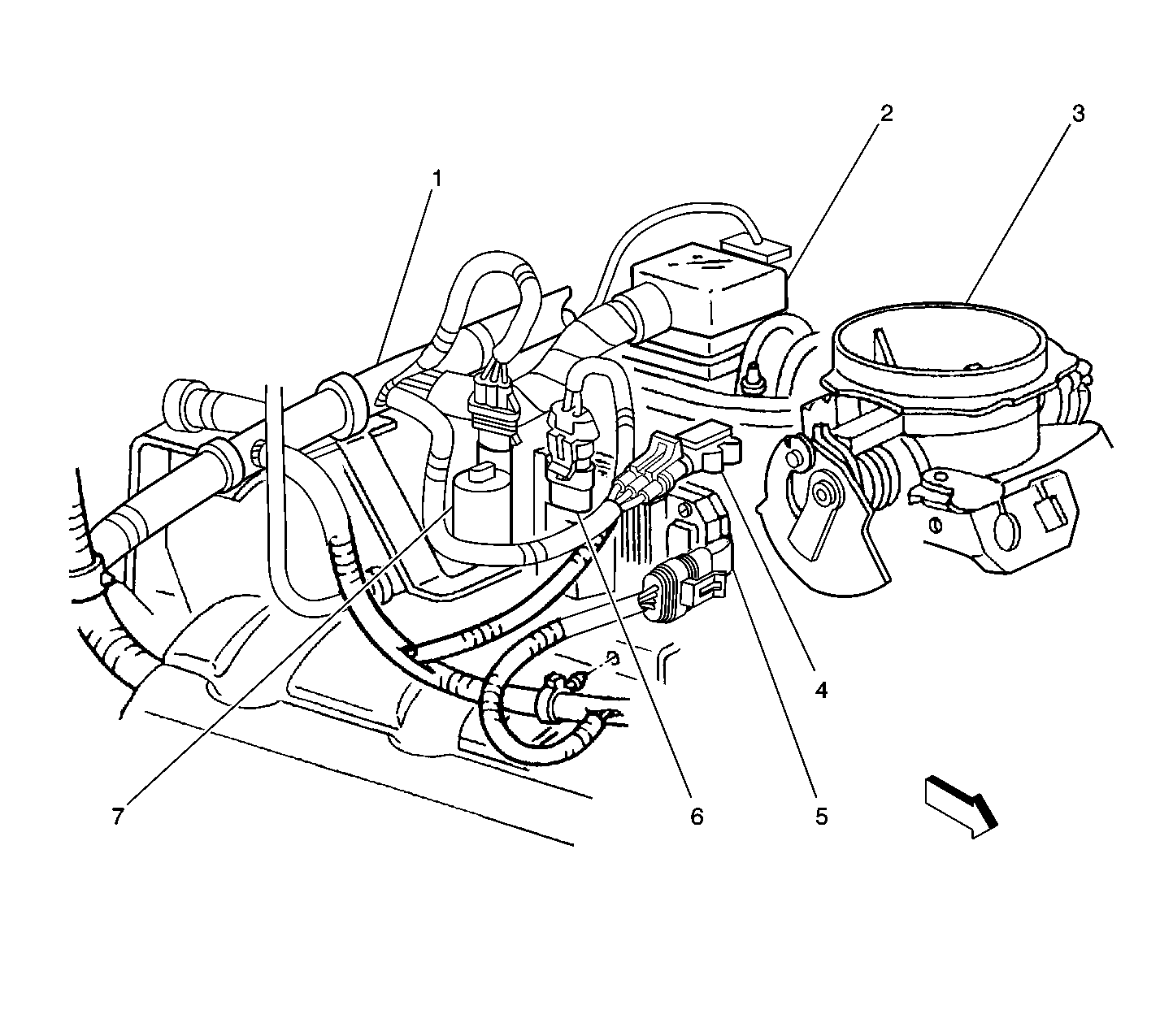

Object Number: 212690  Size: LF
(1)EVAP Pipe
(2)Injector Assembly Electrical Connector
(3)Throttle Body
(4)Manifold Absolute Pressure (MAP) Sensor
(5)Ignition Control (IC) Module
(6)Ignition Coil
(7)Evaporative (EVAP) Canister Purge Valve
in Engine Controls Component Views in Engine Controls - 4.3L in Engine

--

ENG I Fuse (UBEC)

In the Underhood Bussed Electrical Center

Figure 6: UBEC Internal Location View


Object Number: 212233  Size: LF
(1)BTSI Fuse (10 A) (W/ A/T)
(2)B/U LP Fuse (UBEC) (25 A)
(3)Starter Relay (Mini Relay)
(4)IGN B MaxiFuse (50 A)
(5)IGN E Fuse (UBEC) (10 A)
(6)RAP MaxiFuse (40 A)
(7)OXYSEN Fuse (UBEC) (20 A)
(8)IGN A MaxiFuse (UBEC) (40 A)
(9)LR PRK (10 A)
(10)PARKLP Fuse (20 A)
(11)ATC Fuse (20 A)
(12)HVAC Fuse (30 A)
(13)TRCHMSL Fuse (10 A)
(14)HAZLP Fuse (20 A)
(15)VECHMSL Fuse (10 A)
(16)Headlamp Grounding Relay (Micro Relay)
(17)CRANK Fuse (10 A)
(18)STOPLP Fuse (20 A)
(19)TBC Fuse (10 A)
(20)High Mounted Stop Lamp Relay (Micro Relay) (Pickup)
(21)IGN C Fuse (15 A)
(22)FOG LP Fuse (15 A)
(23)Daytime Running Lights Relay Diode
(24) A/C Fuse (10 A)
(25)A/C Compressor Clutch Relay (Micro Relay)
(26)Horn Relay (Micro Relay)
(27)HORN Fuse (15 A)
(28)Daytime Running Lights Relay (Micro Relay)
(29)Fuel Pump Prime Connector
(30)RT HDLP Fuse (10 A)
(31)FR PRK Fuse (10 A)
(32)LT TURN Fuse (Front) (10 A)
(33)RT TURN Fuse (Front) (10 A)
(34)Headlamp Power Relay (Micro Relay)
(35)LT HDLP Fuse (10 A)
(36)RR PRK Fuse (10 A)
(37)VEH B/U Fuse (15 A)
(38)ECM B Fuse (20 A)
(39)RT TRN Fuse (Rear) (10 A)
(40)LT TRN Fuse (Rear) (10 A)
(41)ENG I Fuse (UBEC) (10 A)
(42)ECM I Fuse (UBEC) (15 A)
(43)INT BAT MaxiFuse (50 A)
(44)ABS MaxiFuse (60 A)
(45)Fuel Pump Relay (Micro Relay)
in Starter And Charging Component Views in Engine Electrical in Engine

--

Engine Coolant Temperature Sensor (4.3L Engine)

Front of engine near thermostat housing

Left Side of the Engine Components (4.3L)
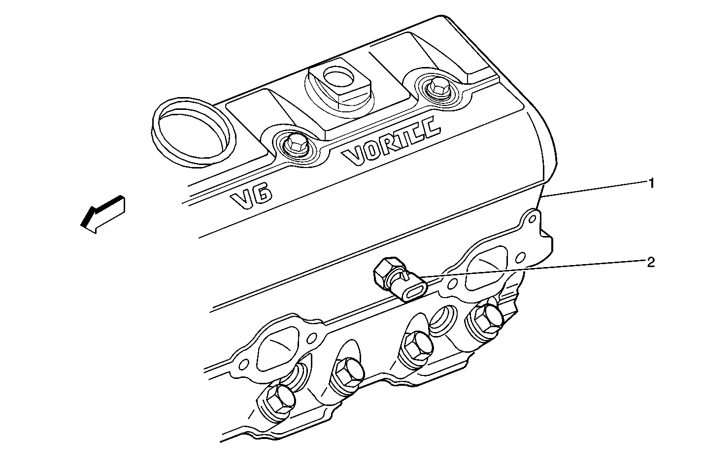

Object Number: 235186  Size: MF
(1)Bank 1 Cylinder Head
(2)Engine Coolant Temperature (ECT) Sensor
in Engine Controls Component Views in Engine Controls - 4.3L in Engine

--

Engine Oil Pressure Gauge Sensor (4.3L Engine)

Top rear of engine below distributor

Throttle Position (TP) Sensor, Idle Air Control (IAC) Valve, and Positive Crankcase Ventilation Valve (PCV)
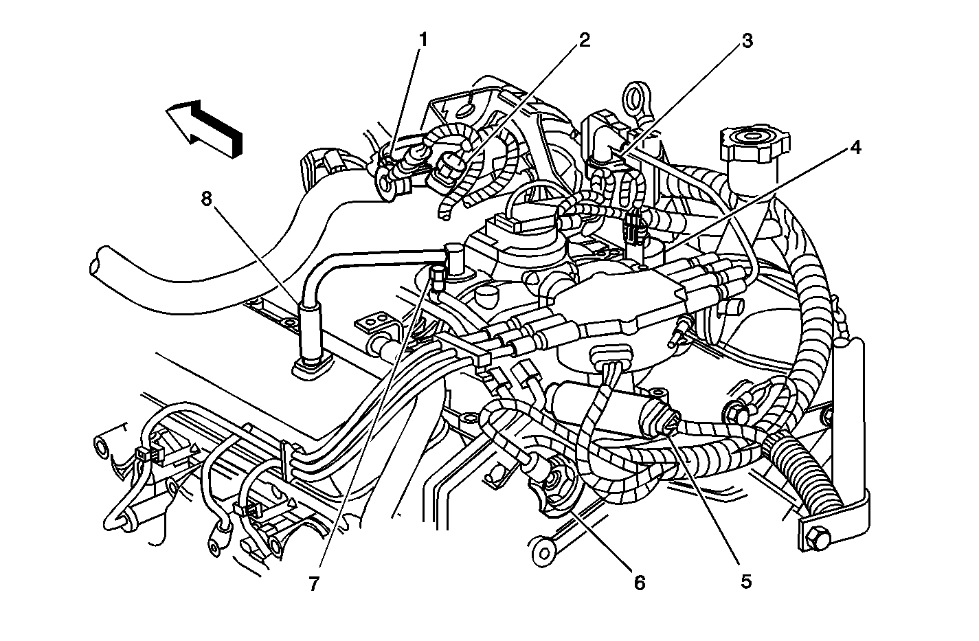

Object Number: 212698  Size: MF
(1)Throttle Position (TP) Sensor
(2)Idle Air Control (IAC) Valve
(3)Ignition Coil
(4)Evaporative (EVAP) Canister Purge Solenoid
(5)Fuel Pump/Oil Pressure Switch
(6)Knock Sensor (KS)
(7)Fuel Pressure Connection Valve
(8)Positive Crankcase Ventilation Valve (PCV)
in Engine Controls Component Views in Engine Controls - 4.3L in Engine

Electrical Diagnosis Connector End Views Page 202-5

Evaporative Emissions Canister Purge Solenoid Valve (4.3L Engine)

Top RH center of engine, near fuel injector connector

MAP, EGR, Purge Solenoid, and Throttle Body


Object Number: 209643  Size: SF
(1)Throttle Body
(2)Exhaust Gas Recirculation (EGR) Valve
(3)Generator
(4)Evaporative Emission (EVAP) Canister Purge Valve
(5)Manifold Absolute Pressure (MAP) Sensor
in Engine Controls Component Views in Engine Controls - 4.3L in Engine

--

Evaporative Emissions Canister Vent Solenoid Valve (4.3L Engine)

Crossmember area of fuel tank, rear center of cross-member behind fuel tank

EVAP Canister and EVAP Vent Valve (4DR Utility and Pickup)
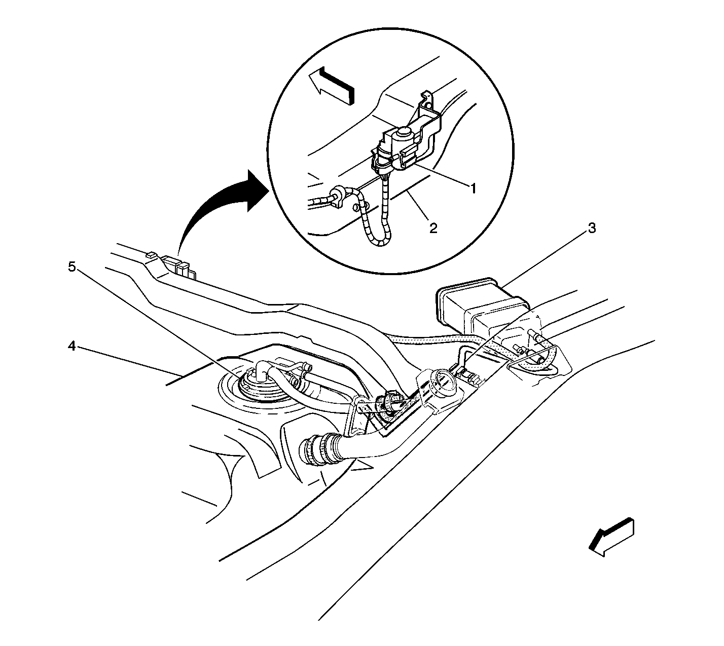

Object Number: 235181  Size: LF
(1)Evaporative (EVAP) Vent Solenoid Valve
(2)Crossmember
(3)EVAP Canister
(4)Fuel Tank
(5)Fuel Tank Sender Assembly
in Engine Controls Component Views in Engine Controls - 4.3L in Engine

--

Exhaust Gas Recirculation Valve (4.3L Engine)

Top front of engine near drive belt

MAP, EGR, Purge Solenoid, and Throttle Body


Object Number: 209643  Size: SF
(1)Throttle Body
(2)Exhaust Gas Recirculation (EGR) Valve
(3)Generator
(4)Evaporative Emission (EVAP) Canister Purge Valve
(5)Manifold Absolute Pressure (MAP) Sensor
in Engine Controls Component Views in Engine Controls - 4.3L in Engine

--

Front Axle Switch

Front axle, right of differential

Figure 3: Front Axle Switch Locator View
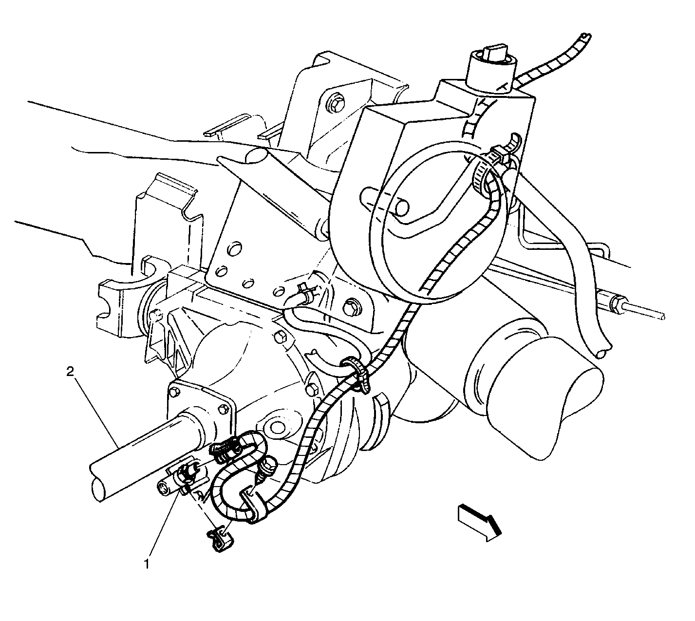

Object Number: 203303  Size: LF
(1)Front Axle Switch (W/ Electric Shift 4WD)
(2)Front axle
in Transfer Case Component Views in Transfer Case in Driveline/ Axle

--

Fuel Level Sensor W/ Fuel Pump (Fuel Sender W/ Pump)

Top of fuel tank, four wire connector

Fuel Tank Pressure Sensor and Fuel Level Sender Assembly
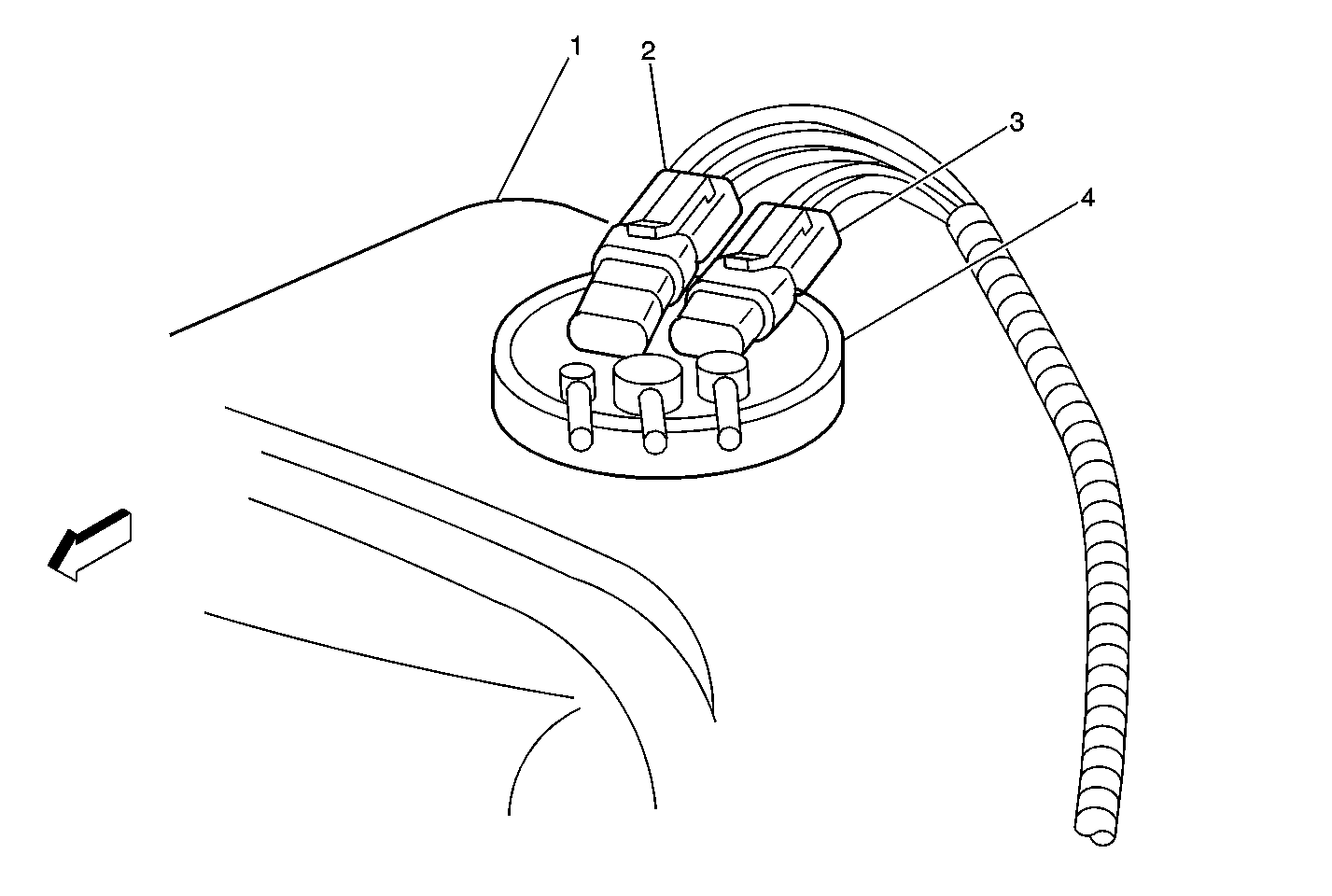

Object Number: 235167  Size: MF
(1)Fuel Tank
(2)Fuel Tank Pressure Sensor Connector
(3)Fuel Level Sender Connector
(4)Fuel Tank Sender Assembly
in Engine Controls Component Views in Engine Controls - 4.3L in Engine

Electrical Diagnosis Connector End Views Page 202-6

Fuel Pump Prime Connector

In the Underhood Bussed Electrical Center

Figure 6: UBEC Internal Location View


Object Number: 212233  Size: LF
(1)BTSI Fuse (10 A) (W/ A/T)
(2)B/U LP Fuse (UBEC) (25 A)
(3)Starter Relay (Mini Relay)
(4)IGN B MaxiFuse (50 A)
(5)IGN E Fuse (UBEC) (10 A)
(6)RAP MaxiFuse (40 A)
(7)OXYSEN Fuse (UBEC) (20 A)
(8)IGN A MaxiFuse (UBEC) (40 A)
(9)LR PRK (10 A)
(10)PARKLP Fuse (20 A)
(11)ATC Fuse (20 A)
(12)HVAC Fuse (30 A)
(13)TRCHMSL Fuse (10 A)
(14)HAZLP Fuse (20 A)
(15)VECHMSL Fuse (10 A)
(16)Headlamp Grounding Relay (Micro Relay)
(17)CRANK Fuse (10 A)
(18)STOPLP Fuse (20 A)
(19)TBC Fuse (10 A)
(20)High Mounted Stop Lamp Relay (Micro Relay) (Pickup)
(21)IGN C Fuse (15 A)
(22)FOG LP Fuse (15 A)
(23)Daytime Running Lights Relay Diode
(24) A/C Fuse (10 A)
(25)A/C Compressor Clutch Relay (Micro Relay)
(26)Horn Relay (Micro Relay)
(27)HORN Fuse (15 A)
(28)Daytime Running Lights Relay (Micro Relay)
(29)Fuel Pump Prime Connector
(30)RT HDLP Fuse (10 A)
(31)FR PRK Fuse (10 A)
(32)LT TURN Fuse (Front) (10 A)
(33)RT TURN Fuse (Front) (10 A)
(34)Headlamp Power Relay (Micro Relay)
(35)LT HDLP Fuse (10 A)
(36)RR PRK Fuse (10 A)
(37)VEH B/U Fuse (15 A)
(38)ECM B Fuse (20 A)
(39)RT TRN Fuse (Rear) (10 A)
(40)LT TRN Fuse (Rear) (10 A)
(41)ENG I Fuse (UBEC) (10 A)
(42)ECM I Fuse (UBEC) (15 A)
(43)INT BAT MaxiFuse (50 A)
(44)ABS MaxiFuse (60 A)
(45)Fuel Pump Relay (Micro Relay)
in Starter And Charging Component Views in Engine Electrical in Engine

--

Fuel Tank Pressure Sensor

Top of fuel tank, three wire connector

Fuel Tank Pressure Sensor and Fuel Level Sender Assembly


Object Number: 235167  Size: MF
(1)Fuel Tank
(2)Fuel Tank Pressure Sensor Connector
(3)Fuel Level Sender Connector
(4)Fuel Tank Sender Assembly
in Engine Controls Component Views in Engine Controls - 4.3L in Engine

--

Generator (4.3L Engine)

RH front of engine

Figure 2: 4.3L Engine Generator And Starter Locator View
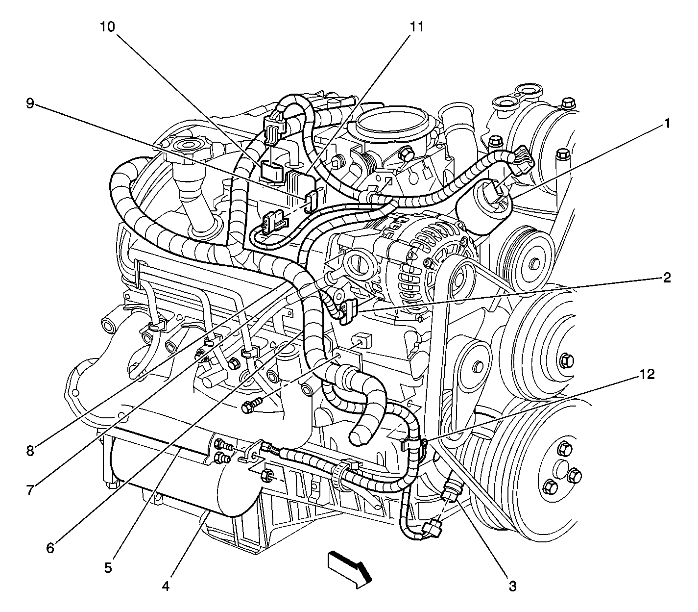

Object Number: 206654  Size: LF
(1)Exhaust Gas Recirculation Valve
(2)Generator
(3)Crankshaft Position Sensor
(4)Starter Motor
(5)Starter Solenoid
(6)Splice S100
(7)Splice S101
(8)Splice S102
(9)Electronic Ignition Control Module
(10)Ignition Coil
(11)Ignition Coil Assembly
in Starter and Charging Component Views in Engine Electrical in Engine

Electrical Diagnosis Connector End Views Page 202-6

Heated Oxygen Sensor, LH Front (Bank 1, Sensor 1) (4.3L Engine)

On the rear of the LH exhaust pipe on the left side of the transmission

HO2S


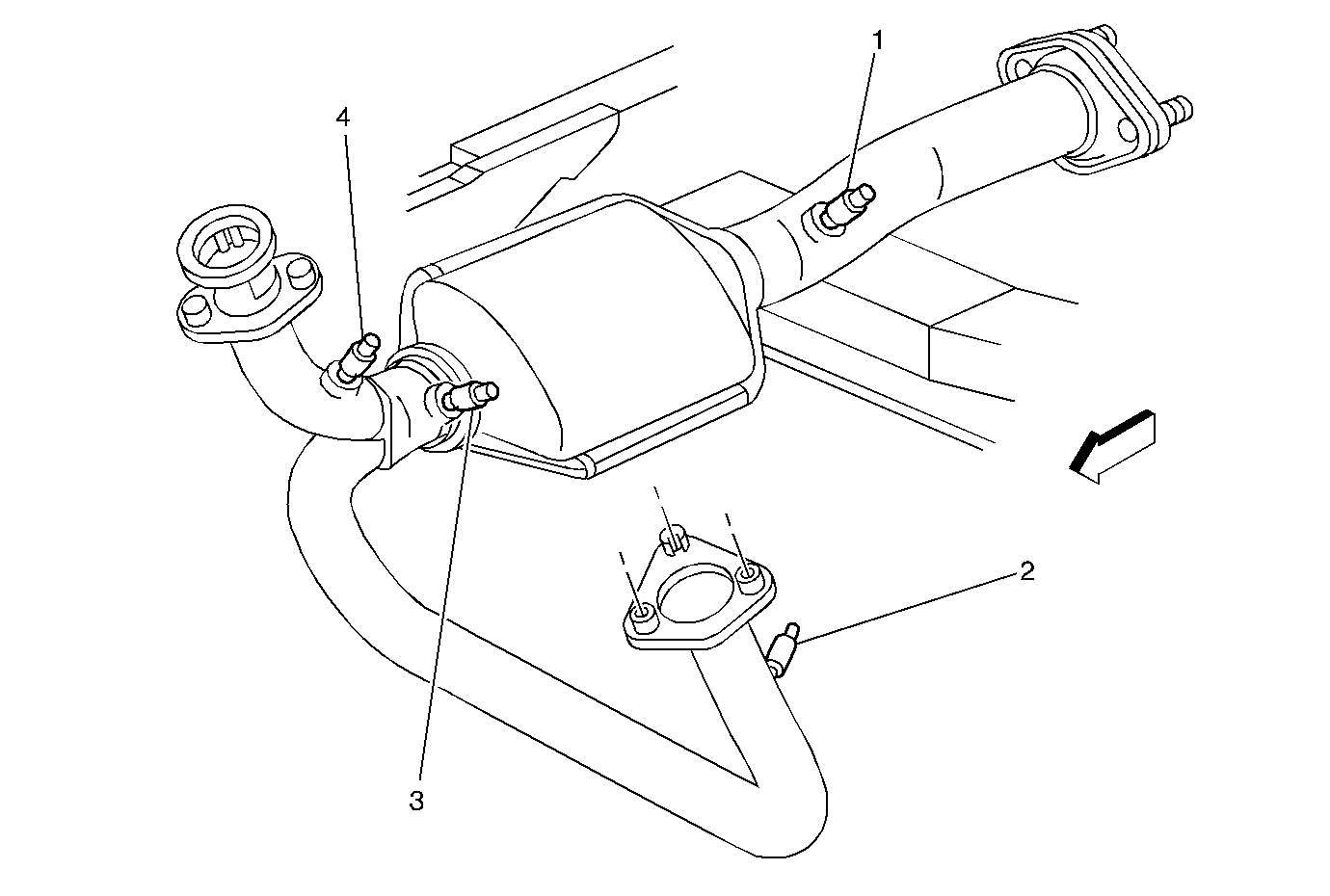
Object Number: 209628  Size: MF
(1)HO2S Bank 1 Sensor 3
(2)HO2S Bank 1 Sensor 1
(3)HO2S Bank 1 Sensor 2 (If Applicable)
(4)HO2S Bank 2 Sensor 1
in Engine Controls Component Views in Engine Controls - 4.3L in Engine

--

Heated Oxygen Sensor, Post-Converter (HO2S Bank 1 Sensor 3) (4.3L Engine)

Rear of the catalytic converter in the exhaust pipe

HO2S


Object Number: 209628  Size: MF
(1)HO2S Bank 1 Sensor 3
(2)HO2S Bank 1 Sensor 1
(3)HO2S Bank 1 Sensor 2 (If Applicable)
(4)HO2S Bank 2 Sensor 1
in Engine Controls Component Views in Engine Controls - 4.3L in Engine

--

Heated Oxygen Sensor, RH Front (HO2S Bank 2 Sensor 1) (4.3L Engine)

RH rear of engine in exhaust pipe

HO2S


Object Number: 209628  Size: MF
(1)HO2S Bank 1 Sensor 3
(2)HO2S Bank 1 Sensor 1
(3)HO2S Bank 1 Sensor 2 (If Applicable)
(4)HO2S Bank 2 Sensor 1
in Engine Controls Component Views in Engine Controls - 4.3L in Engine

--

Heater And A/C Controller

Upper center of instrument panel

--

--

Heater And A/C Controller Connector C2 (W/ Manual A/C) (3 Cavities)

Upper center of instrument panel

--

--

HVAC Fuse 9

In the IP Fuse Block

IP Fuse Block Details in Power Distribution in Electrical Diagnosis

--

Idle Air Control Valve Motor (4.3L Engine)

Top LH side of engine

Throttle Position (TP) Sensor, Idle Air Control (IAC) Valve, and Positive Crankcase Ventilation Valve (PCV)


Object Number: 212698  Size: MF
(1)Throttle Position (TP) Sensor
(2)Idle Air Control (IAC) Valve
(3)Ignition Coil
(4)Evaporative (EVAP) Canister Purge Solenoid
(5)Fuel Pump/Oil Pressure Switch
(6)Knock Sensor (KS)
(7)Fuel Pressure Connection Valve
(8)Positive Crankcase Ventilation Valve (PCV)
in Engine Controls Component Views in Engine Controls - 4.3L in Engine

--

IGN E Fuse (UBEC)

In the Underhood Bussed Electrical Center

Figure 6: UBEC Internal Location View


Object Number: 212233  Size: LF
(1)BTSI Fuse (10 A) (W/ A/T)
(2)B/U LP Fuse (UBEC) (25 A)
(3)Starter Relay (Mini Relay)
(4)IGN B MaxiFuse (50 A)
(5)IGN E Fuse (UBEC) (10 A)
(6)RAP MaxiFuse (40 A)
(7)OXYSEN Fuse (UBEC) (20 A)
(8)IGN A MaxiFuse (UBEC) (40 A)
(9)LR PRK (10 A)
(10)PARKLP Fuse (20 A)
(11)ATC Fuse (20 A)
(12)HVAC Fuse (30 A)
(13)TRCHMSL Fuse (10 A)
(14)HAZLP Fuse (20 A)
(15)VECHMSL Fuse (10 A)
(16)Headlamp Grounding Relay (Micro Relay)
(17)CRANK Fuse (10 A)
(18)STOPLP Fuse (20 A)
(19)TBC Fuse (10 A)
(20)High Mounted Stop Lamp Relay (Micro Relay) (Pickup)
(21)IGN C Fuse (15 A)
(22)FOG LP Fuse (15 A)
(23)Daytime Running Lights Relay Diode
(24) A/C Fuse (10 A)
(25)A/C Compressor Clutch Relay (Micro Relay)
(26)Horn Relay (Micro Relay)
(27)HORN Fuse (15 A)
(28)Daytime Running Lights Relay (Micro Relay)
(29)Fuel Pump Prime Connector
(30)RT HDLP Fuse (10 A)
(31)FR PRK Fuse (10 A)
(32)LT TURN Fuse (Front) (10 A)
(33)RT TURN Fuse (Front) (10 A)
(34)Headlamp Power Relay (Micro Relay)
(35)LT HDLP Fuse (10 A)
(36)RR PRK Fuse (10 A)
(37)VEH B/U Fuse (15 A)
(38)ECM B Fuse (20 A)
(39)RT TRN Fuse (Rear) (10 A)
(40)LT TRN Fuse (Rear) (10 A)
(41)ENG I Fuse (UBEC) (10 A)
(42)ECM I Fuse (UBEC) (15 A)
(43)INT BAT MaxiFuse (50 A)
(44)ABS MaxiFuse (60 A)
(45)Fuel Pump Relay (Micro Relay)
in Starter And Charging Component Views in Engine Electrical in Engine

--

Ignition Coil (Part of Ignition Coil Assembly) (4.3L Engine)

Top RH side of engine

Throttle Position (TP) Sensor, Idle Air Control (IAC) Valve, and Positive Crankcase Ventilation Valve (PCV)


Object Number: 212698  Size: MF
(1)Throttle Position (TP) Sensor
(2)Idle Air Control (IAC) Valve
(3)Ignition Coil
(4)Evaporative (EVAP) Canister Purge Solenoid
(5)Fuel Pump/Oil Pressure Switch
(6)Knock Sensor (KS)
(7)Fuel Pressure Connection Valve
(8)Positive Crankcase Ventilation Valve (PCV)
in Engine Controls Component Views in Engine Controls - 4.3L in Engine

--

Ignition Coil Assembly (4.3 L Engine)

Top RH side of engine

Figure 2: 4.3L Engine Generator And Starter Locator View


Object Number: 206654  Size: LF
(1)Exhaust Gas Recirculation Valve
(2)Generator
(3)Crankshaft Position Sensor
(4)Starter Motor
(5)Starter Solenoid
(6)Splice S100
(7)Splice S101
(8)Splice S102
(9)Electronic Ignition Control Module
(10)Ignition Coil
(11)Ignition Coil Assembly
in Engine Controls Component Views in Engine Controls - 4.3L in Engine

--

Instrument Cluster

In the IP ahead of the steering column

--

Electrical Diagnosis Connector End Views Page 202-10

Intake Air Temperature Sensor (4.3L Engine)

LH front of engine compartment in air intake duct

Mass Air Flow (MAF) Sensor and Intake Air Temperature (IAT) Sensor
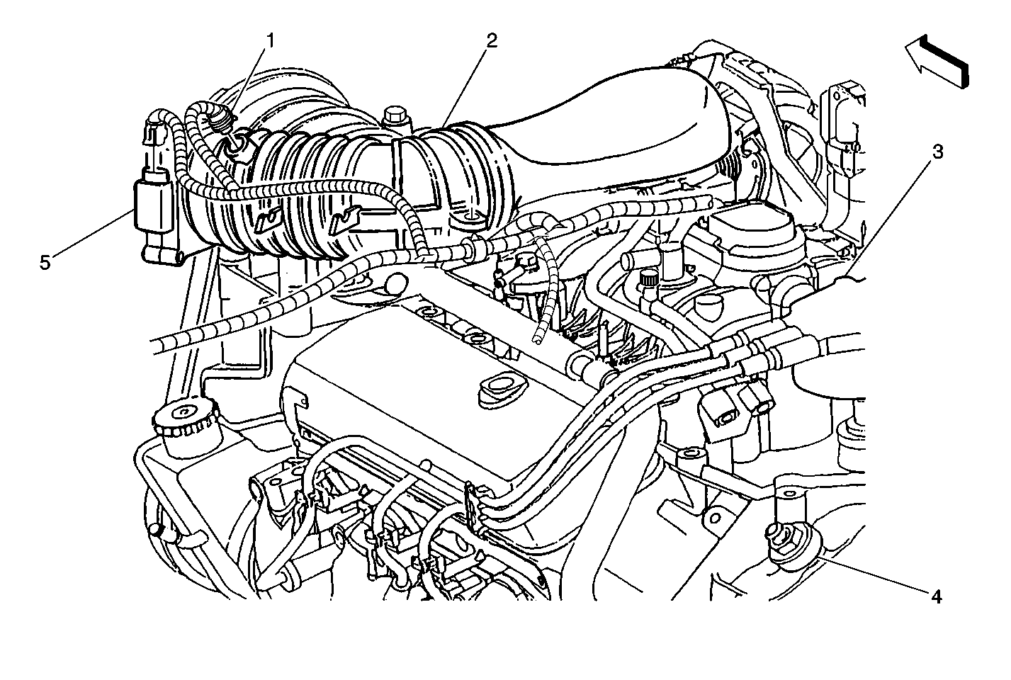

Object Number: 246881  Size: MF
(1)Intake Air Temperature (IAT) Sensor
(2)Air Outlet from Filter
(3)Distributor
(4)Knock Sensor (KS)
(5)Mass Air Flow (MAF) Sensor
in Engine Controls Component Views in Engine Controls - 4.3L in Engine

--

IP Fuse Block

LH side of the IP near the left front side door jamb switch

Figure 8 in Electrical Component Location Views in Electrical Diagnosis

Electrical Diagnosis Connector End Views Page

Knock Sensor (4.3L Engine)

Top rear of engine above transmission bell housing

Mass Air Flow (MAF) Sensor and Intake Air Temperature (IAT) Sensor


Object Number: 246881  Size: MF
(1)Intake Air Temperature (IAT) Sensor
(2)Air Outlet from Filter
(3)Distributor
(4)Knock Sensor (KS)
(5)Mass Air Flow (MAF) Sensor
in Engine Controls Component Views in Engine Controls - 4.3L in Engine

--

Manifold Absolute Pressure Sensor (4.3L Engine)

Top center of engine

MAP, EGR, Purge Solenoid, and Throttle Body


Object Number: 209643  Size: SF
(1)Throttle Body
(2)Exhaust Gas Recirculation (EGR) Valve
(3)Generator
(4)Evaporative Emission (EVAP) Canister Purge Valve
(5)Manifold Absolute Pressure (MAP) Sensor
in Engine Controls Component Views in Engine Controls - 4.3L in Engine

--

Manual Transmission (4.3L Engine)

Behind the engine

--

--

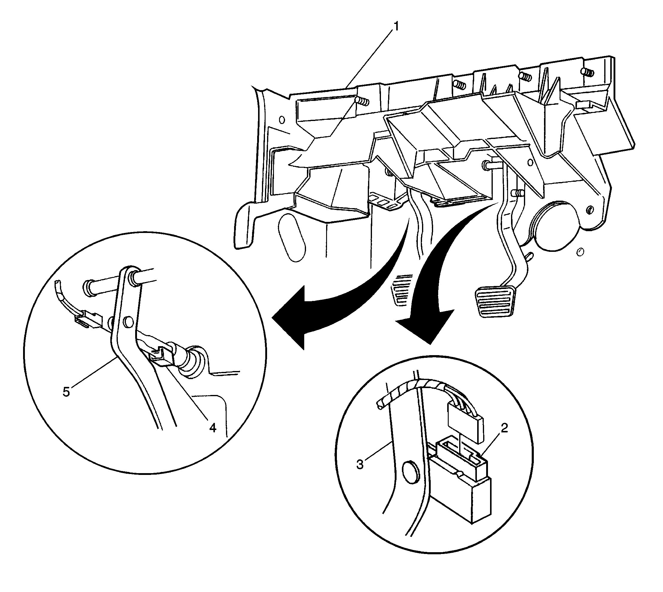
Manual Transmission Clutch Start Switch

On clutch pedal support bracket

Figure1: Floor Pedals Locator View


Object Number: 203295  Size: LF
(1)Dash panel
(2)Stop Lamp Switch
(3)Brake pedal
(4)Manual Transmission Clutch Start Switch
(5)Clutch Pedal
in Starter and Charging Component Views in Engine Electrical in Engine

--

Mass Air Flow Sensor

LH front of engine compartment on air intake duct

Mass Air Flow (MAF) Sensor and Intake Air Temperature (IAT) Sensor


Object Number: 246881  Size: MF
(1)Intake Air Temperature (IAT) Sensor
(2)Air Outlet from Filter
(3)Distributor
(4)Knock Sensor (KS)
(5)Mass Air Flow (MAF) Sensor
in Engine Controls Component Views in Engine Controls - 4.3L in Engine

--

OXYSEN Fuse

In the Underhood Bussed Electrical Center

Figure 6: UBEC Internal Location View


Object Number: 212233  Size: LF
(1)BTSI Fuse (10 A) (W/ A/T)
(2)B/U LP Fuse (UBEC) (25 A)
(3)Starter Relay (Mini Relay)
(4)IGN B MaxiFuse (50 A)
(5)IGN E Fuse (UBEC) (10 A)
(6)RAP MaxiFuse (40 A)
(7)OXYSEN Fuse (UBEC) (20 A)
(8)IGN A MaxiFuse (UBEC) (40 A)
(9)LR PRK (10 A)
(10)PARKLP Fuse (20 A)
(11)ATC Fuse (20 A)
(12)HVAC Fuse (30 A)
(13)TRCHMSL Fuse (10 A)
(14)HAZLP Fuse (20 A)
(15)VECHMSL Fuse (10 A)
(16)Headlamp Grounding Relay (Micro Relay)
(17)CRANK Fuse (10 A)
(18)STOPLP Fuse (20 A)
(19)TBC Fuse (10 A)
(20)High Mounted Stop Lamp Relay (Micro Relay) (Pickup)
(21)IGN C Fuse (15 A)
(22)FOG LP Fuse (15 A)
(23)Daytime Running Lights Relay Diode
(24) A/C Fuse (10 A)
(25)A/C Compressor Clutch Relay (Micro Relay)
(26)Horn Relay (Micro Relay)
(27)HORN Fuse (15 A)
(28)Daytime Running Lights Relay (Micro Relay)
(29)Fuel Pump Prime Connector
(30)RT HDLP Fuse (10 A)
(31)FR PRK Fuse (10 A)
(32)LT TURN Fuse (Front) (10 A)
(33)RT TURN Fuse (Front) (10 A)
(34)Headlamp Power Relay (Micro Relay)
(35)LT HDLP Fuse (10 A)
(36)RR PRK Fuse (10 A)
(37)VEH B/U Fuse (15 A)
(38)ECM B Fuse (20 A)
(39)RT TRN Fuse (Rear) (10 A)
(40)LT TRN Fuse (Rear) (10 A)
(41)ENG I Fuse (UBEC) (10 A)
(42)ECM I Fuse (UBEC) (15 A)
(43)INT BAT MaxiFuse (50 A)
(44)ABS MaxiFuse (60 A)
(45)Fuel Pump Relay (Micro Relay)
in Starter And Charging Component Views in Engine Electrical in Engine

--

Pressure Control Solenoid (PC SOL) Valve

Inside the automatic transmission


Object Number: 62792  Size: LF

(36)Vehicle Speed Sensor
(66)Torque Converter Clutch Solenoid Valve
(69)Automatic Transmission Fluid Pressure Manual Valve Position Switch
(367a)1-2 Shift Solenoid Valve
(367b)2-3 Shift Solenoid Valve
(377)Pressure Control Solenoid Valve
(394)3-2 Shift Solenoid Valve Assembly
(396)Torque Converter Clutch Pulse Width Modulation Solenoid Valve
in Automatic Transmission - 4L60E in Transmission/ Transaxle

Automatic Transmission Internal Connector End Views in Automatic Transmission - 4L60E in Transmission/ Transaxle

RDO BATT Fuse 19

In the IP Fuse Block

IP Fuse Block Details in Power Distribution in Electrical Diagnosis

--

Stop Lamp Switch

Mounted on brake pedal

Figure1: Floor Pedals Locator View


Object Number: 203295  Size: LF
(1)Dash panel
(2)Stop Lamp Switch
(3)Brake pedal
(4)Manual Transmission Clutch Start Switch
(5)Clutch Pedal
in Starter and Charging Component Views in Engine Electrical in Engine

Electrical Diagnosis Connector End Views Page 202-11

Throttle Position Sensor (4.3L Engine)

Top LH side of engine

Throttle Position (TP) Sensor, Idle Air Control (IAC) Valve, and Positive Crankcase Ventilation Valve (PCV)


Object Number: 212698  Size: MF
(1)Throttle Position (TP) Sensor
(2)Idle Air Control (IAC) Valve
(3)Ignition Coil
(4)Evaporative (EVAP) Canister Purge Solenoid
(5)Fuel Pump/Oil Pressure Switch
(6)Knock Sensor (KS)
(7)Fuel Pressure Connection Valve
(8)Positive Crankcase Ventilation Valve (PCV)
in Engine Controls Component Views in Engine Controls - 4.3L in Engine

--

Torque Converter Clutch Pule Width Modulation Solenoid (TCC PWM SOL) Valve

Inside the automatic transmission


Object Number: 62792  Size: LF

(36)Vehicle Speed Sensor
(66)Torque Converter Clutch Solenoid Valve
(69)Automatic Transmission Fluid Pressure Manual Valve Position Switch
(367a)1-2 Shift Solenoid Valve
(367b)2-3 Shift Solenoid Valve
(377)Pressure Control Solenoid Valve
(394)3-2 Shift Solenoid Valve Assembly
(396)Torque Converter Clutch Pulse Width Modulation Solenoid Valve
in Automatic Transmission - 4L60E in Transmission/ Transaxle

Automatic Transmission Internal Connector End Views in Automatic Transmission - 4L60E in Transmission/ Transaxle

Torque Converter Clutch Solenoid (TCC SOL) Valve

Inside the automatic transmission


Object Number: 62792  Size: LF

(36)Vehicle Speed Sensor
(66)Torque Converter Clutch Solenoid Valve
(69)Automatic Transmission Fluid Pressure Manual Valve Position Switch
(367a)1-2 Shift Solenoid Valve
(367b)2-3 Shift Solenoid Valve
(377)Pressure Control Solenoid Valve
(394)3-2 Shift Solenoid Valve Assembly
(396)Torque Converter Clutch Pulse Width Modulation Solenoid Valve
in Automatic Transmission - 4L60E in Transmission/ Transaxle

--

Transfer Case Control Module (TCCM) (NP1)

Behind Center of Instrument Panel

Figure 5: Shift Control Module Locator View
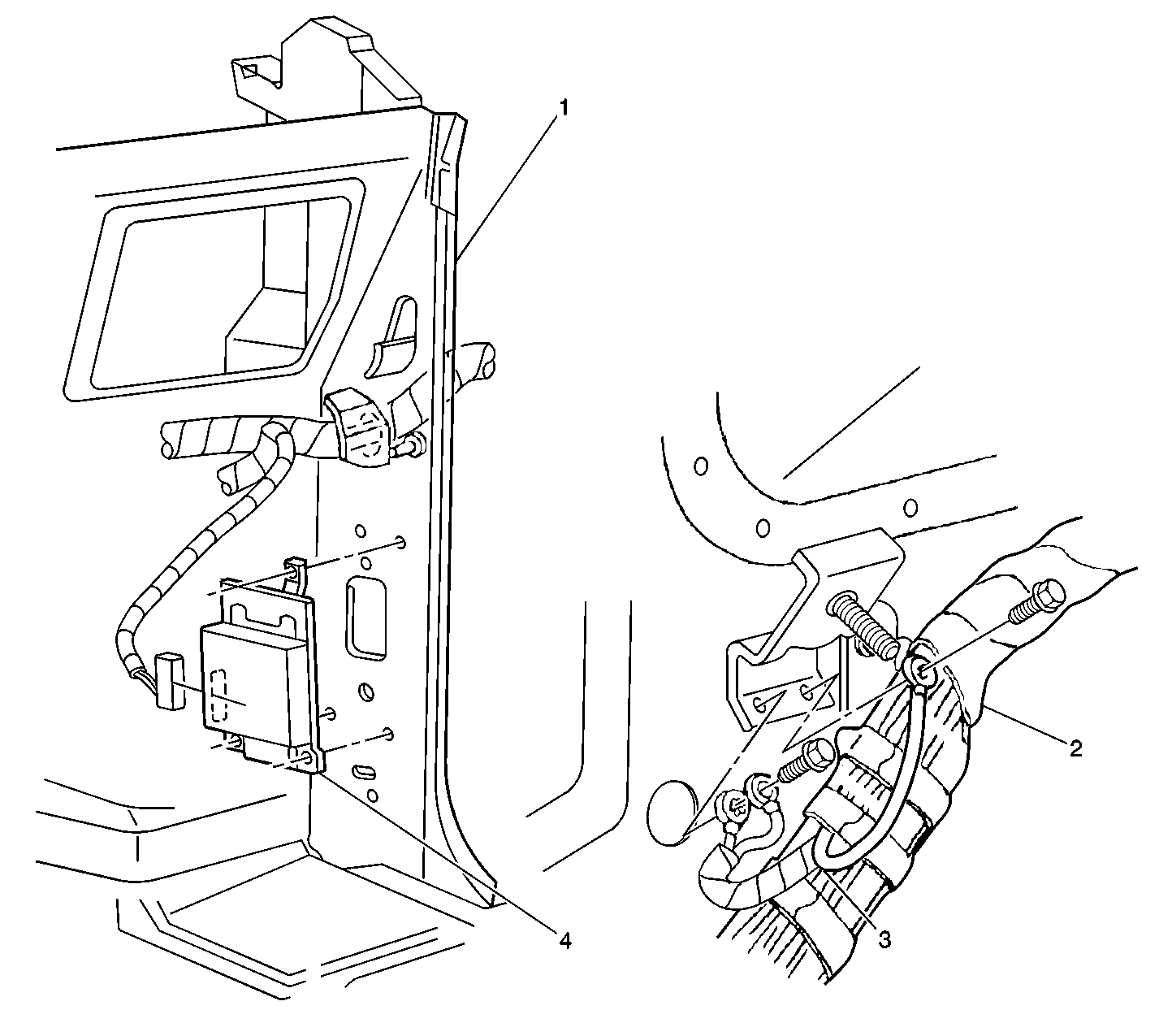

Object Number: 209106  Size: LF
(1)Side cowl panel
(2)Body harness to Connector C203
(3)Grounds G203, G204, and G205
(4)Transfer Case Control Module (S4WD)
in Transfer Case Component Views in Transfer Case in Driveline/ Axle

Electrical Diagnosis Connector End Views Page 202-12

Transfer Case Select Switch

Front center of instrument panel above and to the left of the radio

Figure 4: Instrument Panel Center Switch Locator View
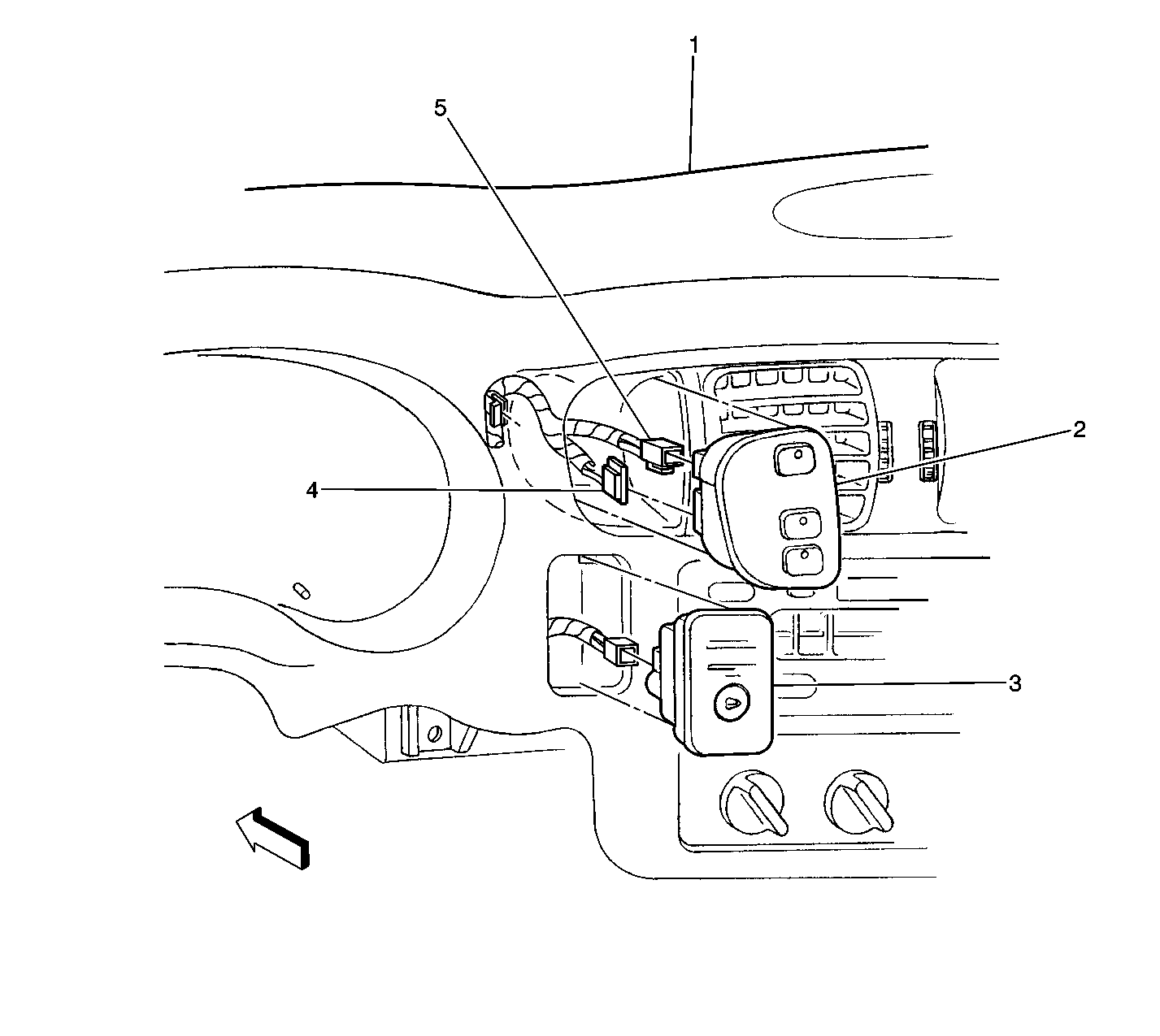

Object Number: 208249  Size: LF
(1)Instrument Panel (IP)
(2)Transfer Case Select Switch (W/ Electric Shift 4WD)
(3)Supplemental Restraint IP Module Switch
(4)Transfer Case Select Switch Connector C2
(5)Transfer Case Select Switch Connector C1
in Transfer Case Component Views in Transfer Case in Driveline/ Axle

--

Transfer Case Select Switch (W/ Electric Shift 4WD) Connector C2 (4 Cavities)

Front center of instrument panel above and to the left of the radio

Figure 4: Instrument Panel Center Switch Locator View


Object Number: 208249  Size: LF
(1)Instrument Panel (IP)
(2)Transfer Case Select Switch (W/ Electric Shift 4WD)
(3)Supplemental Restraint IP Module Switch
(4)Transfer Case Select Switch Connector C2
(5)Transfer Case Select Switch Connector C1
in Transfer Case Component Views in Transfer Case in Driveline/ Axle

Electrical Diagnosis Connector End Views Page 202-12

Transmission Fluid Temperature (TFT) Sensor

Inside the automatic transmission

--

--

Transmission Range Switch (Park/Neutral Position And Backup Lamp Switch)

LH side of transmission

Figure 3: Transmission Range Switch Locator View
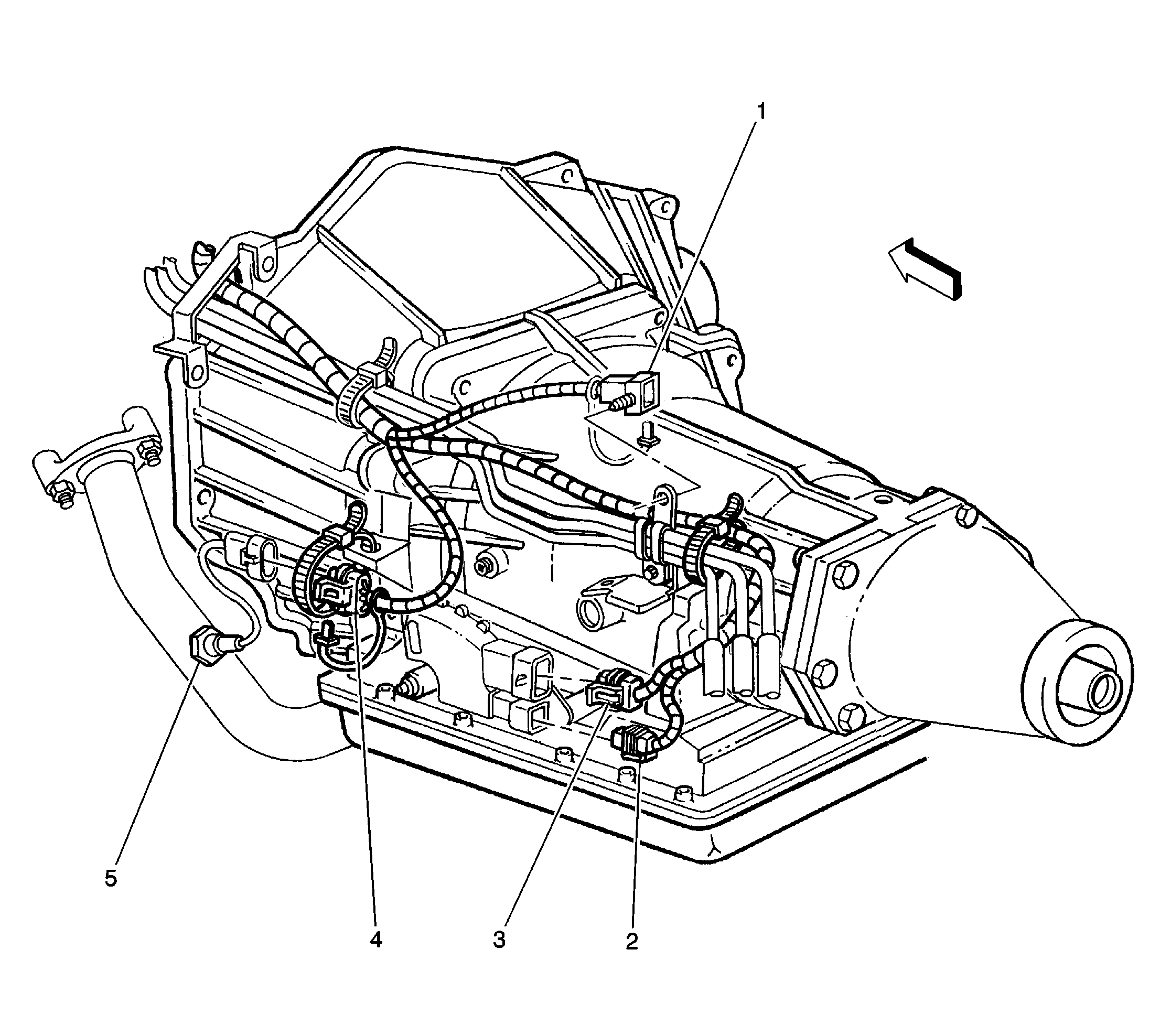

Object Number: 206877  Size: LF
(1)Connector C104 (Engine Harness to Chassis Harness)
(2)Transmission Range Switch Connector C2
(3)Transmission Range Switch Connector C1
(4)Connector C105 (4.3L Engine Harness to LH Front Heated Oxygen Sensor Harness)
(5)Heated Oxygen Sensor, LH Front (Bank 1, Sensor 1) (4.3L Engine)
in Starter and Charging Component Views in Engine Electrical in Engine

--

Transmission Range Switch (Park/Neutral Position And Backup Lamp Switch) Connector C1

LH side of transmission

Figure 3: Transmission Range Switch Locator View


Object Number: 206877  Size: LF
(1)Connector C104 (Engine Harness to Chassis Harness)
(2)Transmission Range Switch Connector C2
(3)Transmission Range Switch Connector C1
(4)Connector C105 (4.3L Engine Harness to LH Front Heated Oxygen Sensor Harness)
(5)Heated Oxygen Sensor, LH Front (Bank 1, Sensor 1) (4.3L Engine)
in Starter and Charging Component Views in Engine Electrical in Engine

--

Transmission Range Switch (Park/Neutral Position And Backup Lamp Switch) Connector C2

LH side of transmission

Figure 3: Transmission Range Switch Locator View


Object Number: 206877  Size: LF
(1)Connector C104 (Engine Harness to Chassis Harness)
(2)Transmission Range Switch Connector C2
(3)Transmission Range Switch Connector C1
(4)Connector C105 (4.3L Engine Harness to LH Front Heated Oxygen Sensor Harness)
(5)Heated Oxygen Sensor, LH Front (Bank 1, Sensor 1) (4.3L Engine)
in Starter and Charging Component Views in Engine Electrical in Engine

--

Truck Body Control Module

Lower rear of IP on the heater assembly

Figure 8 in Electrical Component Location Views in Electrical Diagnosis

--

Truck Body Control Module Connector C1 (24 Cavities)

Lower rear of IP on the heater assembly

--

Electrical Diagnosis Connector End Views Page 202-14

Truck Body Control Module Connector C2 (24 Cavities)

Lower rear of IP on the heater assembly

--

Electrical Diagnosis Connector End Views Page 202-15

Underhood Bussed Electrical Center (UBEC)

Over left front fender well

--

--

Underhood Bussed Electrical Center (UBEC) Connector C1 (Body, 68 Cavities)

Below the Underhood Bussed Electrical Center

--

--

Underhood Bussed Electrical Center (UBEC) Connector C2 (4.3L Engine, 68 Cavities)

Below the Underhood Bussed Electrical Center

--

--

Underhood Bussed Electrical Center (UBEC) Connector C3 (Chassis, 32 Cavities)

Below the Underhood Bussed Electrical Center

--

--

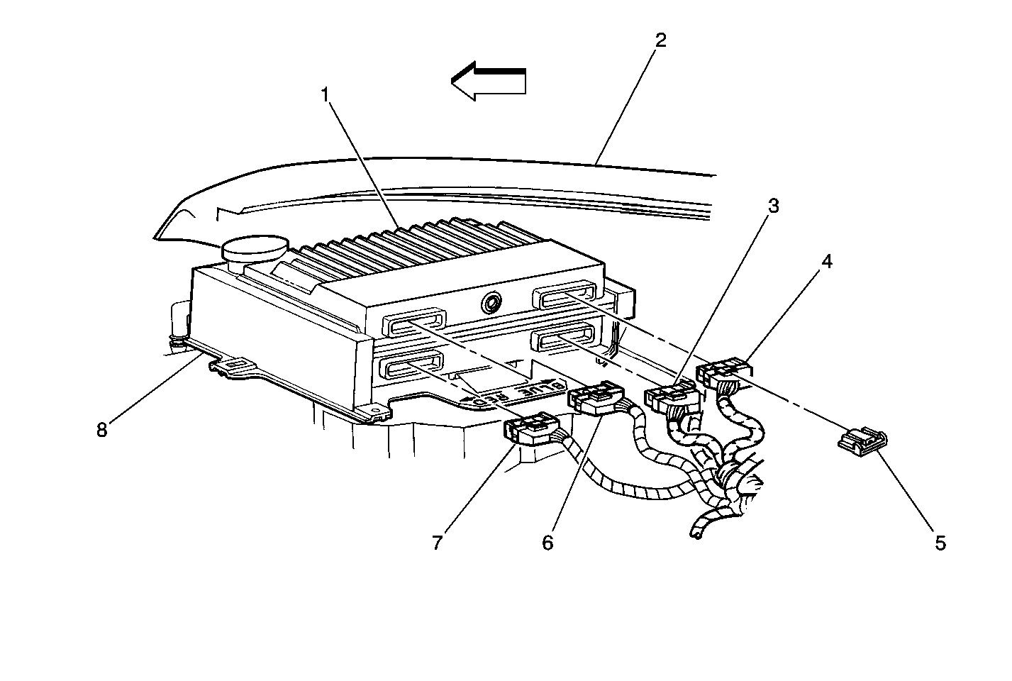
Vehicle Control Module (VCM) (4.3L Engine)

RH side of engine compartment

VCM


Object Number: 246882  Size: MF
(1)Vehicle Control Module (VCM)
(2)Right Front Fender
(3)VCM Connector (Blue)
(4)VCM Connector (Clear)
(5)VCM Connector Retainer
(6)VCM Connector (Black)
(7)VCM Connector (Red)
(8)VCM Retainer
in Engine Controls Component Views in Engine Controls - 4.3L in Engine

--

Vehicle Control Module (VCM) (4.3L Engine) Connector C1 (32 Cavities)

RH side of engine compartment

VCM


Object Number: 246882  Size: MF
(1)Vehicle Control Module (VCM)
(2)Right Front Fender
(3)VCM Connector (Blue)
(4)VCM Connector (Clear)
(5)VCM Connector Retainer
(6)VCM Connector (Black)
(7)VCM Connector (Red)
(8)VCM Retainer
in Engine Controls Component Views in Engine Controls - 4.3L in Engine

VCM Connector End Views in Engine Controls - 4.3L in Engine

Vehicle Control Module (VCM) (4.3L Engine) Connector C2 (32 Cavities)

RH side of engine compartment

VCM


Object Number: 246882  Size: MF
(1)Vehicle Control Module (VCM)
(2)Right Front Fender
(3)VCM Connector (Blue)
(4)VCM Connector (Clear)
(5)VCM Connector Retainer
(6)VCM Connector (Black)
(7)VCM Connector (Red)
(8)VCM Retainer
in Engine Controls Component Views in Engine Controls - 4.3L in Engine

VCM Connector End Views in Engine Controls - 4.3L in Engine

Vehicle Control Module (VCM) (4.3L Engine) Connector C3 (32 Cavities)

RH side of engine compartment

VCM


Object Number: 246882  Size: MF
(1)Vehicle Control Module (VCM)
(2)Right Front Fender
(3)VCM Connector (Blue)
(4)VCM Connector (Clear)
(5)VCM Connector Retainer
(6)VCM Connector (Black)
(7)VCM Connector (Red)
(8)VCM Retainer
in Engine Controls Component Views in Engine Controls - 4.3L in Engine

VCM Connector End Views in Engine Controls - 4.3L in Engine

Vehicle Control Module (VCM) (4.3L Engine) Connector C4 (24 Cavities)

RH side of engine compartment

VCM


Object Number: 246882  Size: MF
(1)Vehicle Control Module (VCM)
(2)Right Front Fender
(3)VCM Connector (Blue)
(4)VCM Connector (Clear)
(5)VCM Connector Retainer
(6)VCM Connector (Black)
(7)VCM Connector (Red)
(8)VCM Retainer
in Engine Controls Component Views in Engine Controls - 4.3L in Engine

VCM Connector End Views in Engine Controls - 4.3L in Engine

Vehicle Speed Sensor (VSS) (4.3L Engine W/ A/T, W/O Transfer Case)

RH rear of automatic transmission

--

Electrical Diagnosis Connector End Views Page 202-15

Vehicle Speed Sensor (VSS) (4.3L Engine W/ Electric Shift 4WD)

LH Rear of Electric Shift Transfer Case

--

Electrical Diagnosis Connector End Views Page 202-15

Vehicle Speed Sensor (VSS) (4.3L Engine W/ M/T W/O Transfer Case)

LH rear of manual transmission

--

Electrical Diagnosis Connector End Views Page 202-15

C100 (Engine Harness to Oxygen Sensor Harness) (4.3L Engine, 6 Cavities)

RH rear of engine compartment, near the accumulator

--

--

C101 (Engine Harness to Body Harness) (4.3L Engine, 10 Cavities)

RH engine compartment, near VCM

--

Electrical Diagnosis Connector End Views Page 202-18

C104 (Chassis to 4.3L Engine Harness) (6 Cavities)

LH side of transmission

--

Electrical Diagnosis Connector End Views Page 202-19

C105 (Engine Harness to LH Front Heated Oxygen Sensor Pigtail Connector) (4.3L Engine, W/ A/T) (4 Cavities)

On the LH side of the transmission

--

--

C105 (Engine Harness to LH Front Heated Oxygen Sensor Pigtail Connector) (4.3L Engine, W/ M/T) (4 Cavities)

On the LH side of the transmission

--

--

C114 (W/ Electric Shift 4WD, Body harness to front axle switch extension harness) (2 Cavities)

LH center of engine compartment, near the electronic brake control module)

Figure 6: LH Front Fender Area Locator View
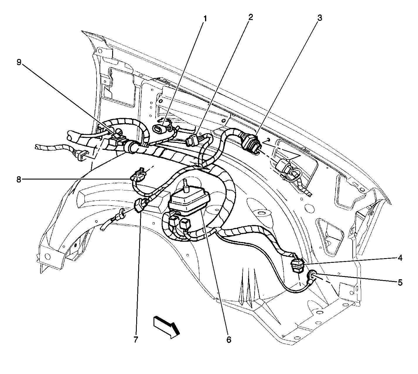

Object Number: 209583  Size: LF
(1)Electronic Brake Control Module Connector C1
(2)Electronic Brake Control Module Connector C2
(3)Connector C109 (Body Harness to 4WAL Harness)
(4)Ground G110
(5)Windshield Washer Pump
(6)Underhood Bussed Electrical Center (UBEC)
(7)Connector C114 (Body Harness to Front Axle Switch, W/ Electric Shift 4WD)
(8)Brake Pressure Warning Switch
(9)Connector C108 (Body Harness to S4WD Extension Harness)
in Transfer Case Component Views in Transfer Case in Driveline/ Axle

Electrical Diagnosis Connector End Views Page

C116 (M to M) (W/ A/T and Transfer Case) (2 Cavities)

Near the top rear of the automatic transmission

Figure 1: Electric Shift Transfer Case Locator View


Object Number: 203300  Size: LF
(1)Connector C116 (Engine Harness to VSS Extension Harness)
(2)Electric Shift Transfer Case
(3)Vehicle Speed Sensor (W/ Electric Shift 4WD)
(4)Electric Shift Transfer Case extension harness connector
in Transfer Case Component Views in Transfer Case in Driveline/ Axle

--

C116 (M to M) (W/ M/T and Transfer Case) (2 Cavities)

Near the LH rear of the manual transmission

Figure 1: Electric Shift Transfer Case Locator View


Object Number: 203300  Size: LF
(1)Connector C116 (Engine Harness to VSS Extension Harness)
(2)Electric Shift Transfer Case
(3)Vehicle Speed Sensor (W/ Electric Shift 4WD)
(4)Electric Shift Transfer Case extension harness connector
in Transfer Case Component Views in Transfer Case in Driveline/ Axle

--

C125 (Oxygen Sensor Harness to Post-Converter Heated Oxygen Sensor Pigtail Connector) (4.3L Engine) (4 Cavities)

Chassis harness near the Post-Converter (Bank 1, Sensor 3) Heated Oxygen Sensor

--

--

C126 (Oxygen Sensor Harness to RH Front Heated Oxygen Sensor Pigtail Connector) (4.3L Engine) (4 Cavities)

Chassis harness near the RH Front (Bank 2, Sensor 1) Heated Oxygen Sensor

--

--

C175 (Engine Harness to Automatic Transmission Connector) (4.3L Engine) (13 Cavities)

RH rear of the automatic transmission

--

Automatic Transmission Inline Harness Connector End View in Automatic Transmission - 4L60E in Transmission/ Transaxle

C203 (Body Harness to IP Harness) (116 Cavities)

RH side of dash

Figure 9 in Electrical Component Location Views in Electrical Diagnosis

Electrical Diagnosis Connector End Views Page 202-26

G102 (Circuit 350, 4.3L Engine Harness)

LH rear of engine block

--

--

G103 (Circuit 351, 4.3L Engine Harness)

LH rear of engine block

--

--

G104 (Circuit 450, 4.3L Engine Harness)

RH rear of engine block

--

--

G105 (Circuit 451, 4.3L Engine Harness)

RH rear of engine block

--

--

G200 (Circuit 1850, Body Harness)

LH front of dash panel, above grommet P100

--

--

G201 (Circuit 1850, Body Harness)

LH front of dash panel, above grommet P100

--

--

G402 (Circuit 1750, Chassis Harness)

Inside rear of LH Frame Rail

--

--

P100 (IP Bulkhead Pass-Through)

LH rear of engine compartment, on cowl

--

--

S100 (Circuit 452, 4.3L Engine Harness)

Between the breakouts for the starter and the generator, 4 cm from the breakout to the generator

Figure 1 in Electrical Component Location Views in Electrical Diagnosis

--

S101 (Circuit 474, 4.3L Engine Harness)

Between the breakouts to the generator and the fuel injector connector, 5 cm from the breakout to the generator

Figure 1 in Electrical Component Location Views in Electrical Diagnosis

--

S102 (Circuit 470, 4.3L Engine Harness)

Between the breakouts for the generator and the fuel injection connectors, 5 cm from the breakout to the fuel injection connector

Figure 1 in Electrical Component Location Views in Electrical Diagnosis

--

S103 (Circuit 350, 4.3L Engine Harness W/ A/C)

In the breakout to the A/C compressor and cutoff switch, 7.5 cm from the breakout

Figure 1 in Electrical Component Location Views in Electrical Diagnosis

--

S104 (Circuit 59, 4.3L Engine Harness W/ A/C)

In the breakout to the A/C compressor and cutoff switch, 7.5 cm from the breakout

Figure 1 in Electrical Component Location Views in Electrical Diagnosis

--

S106 (Circuit 351, 4.3L Engine Harness)

Between the breakouts to the connector for the rear oxygen sensors and the body harness connector, 6.5 cm from the breakout to the oxygen sensor connector

--

--

S113 (Circuit 1020, Body Harness)

Between the Blower Motor breakout and the Blower Motor Relay breakout, 13 cm from the breakout to the blower motor

--

--

S113 (Circuit 1020, Body Harness)

Between the breakouts to the VCM and the blower motor relay, 13 cm from the breakout to the VCM

--

--

S133 (Circuit 839, Automatic Transmission harness)

Inside the Automatic Transmission-A/T only.

--

--

S138 (Circuit 420, Body harness)

Between the Blower Motor Resistor breakout and the Windshield Wiper Motor breakout, 6 cm from the breakout to the resistor.

--

--

S140 (Circuit 450, 4.3L Engine Harness W/ A/T)

15 cm from the end of vehicle speed sensor connector

--

--

S140 (Circuit 450, 4.3L Engine Harness W/ M/T)

20 cm from the end of vehicle speed sensor connector

--

--

S150 (Circuit 539, 4.3L Engine Oxygen Sensor Harness)

Between the breakouts to the RH Front and the post-catalytic oxygen, 10 cm from the breakout to the RH Front sensor

--

--

S151 (Circuit 350, 4.3L Engine Oxygen Sensor Harness)

Between the In-Line Connector and the RH Front oxygen sensor, 10 cm from the breakout to the RH Front sensor

--

--

S152 (Circuit 351, 413, and 451, 4.3L Engine Harness)

Between the breakouts for the LR and RR engine block grounds, 15 cm from the breakout to the LR engine grounds

--

--

SP200 (Circuits 41, 241, 341, 817 Splice Pack, Body Harness)

Strapped to the body harness in the center front of dash area, to the right of SP204

--

--

SP201 (Data Link Connector Spice Pack, Body Harness)

LH side of dash panel, below IP Fuse Block

--

--

SP202 (379, 1850 Splice Pack, Body Harness)

Strapped to body harness at LH center of the front of dash area

--

--

SP422 (Pickup Chassis W/ 4.3L Engine, Circuit 470)

On the LH frame rail behind the crossmember at the transmission

--

--