Removal Procedure
- Disconnect the battery negative cable.
- Remove the drive belt.
- Remove the air conditioning compressor, if equipped, and set it aside.
- Remove the power steering pump and set it aside, using the following procedure:
- Remove the exhaust pipe from the exhaust manifold.
- Remove the oil level indicator tube.
- Disconnect the oxygen sensor electrical connection.
- Remove the exhaust manifold and the gasket.
- Clean all sealing surfaces.
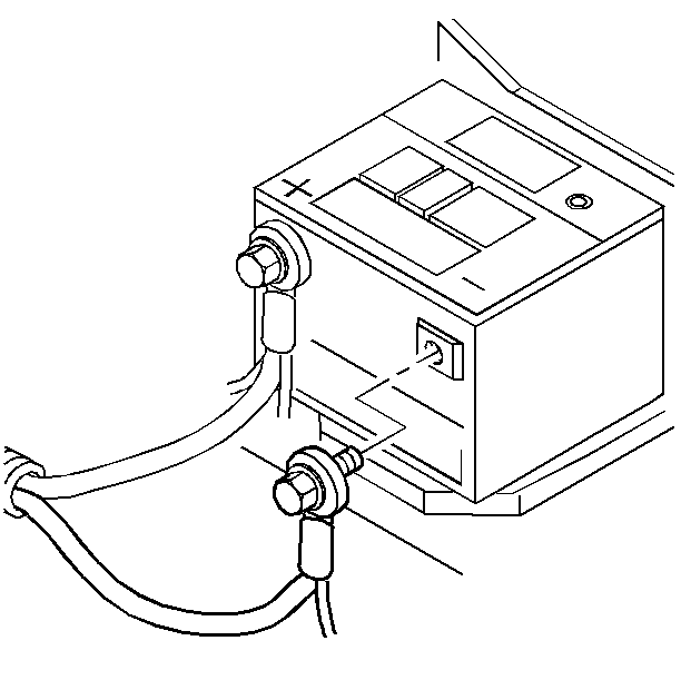
Caution: Before servicing any electrical component, the ignition and start switch must be in the OFF or LOCK position and all electrical loads must be OFF, unless instructed otherwise in these procedures. If a tool or equipment could easily come in contact with a live exposed electrical terminal, also disconnect the negative battery cable. Failure to follow these precautions may cause personal injury and/or damage to the vehicle or its components.
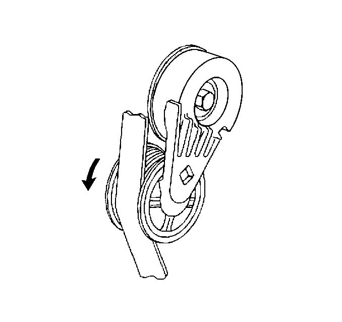
Refer to Drive Belt Replacement
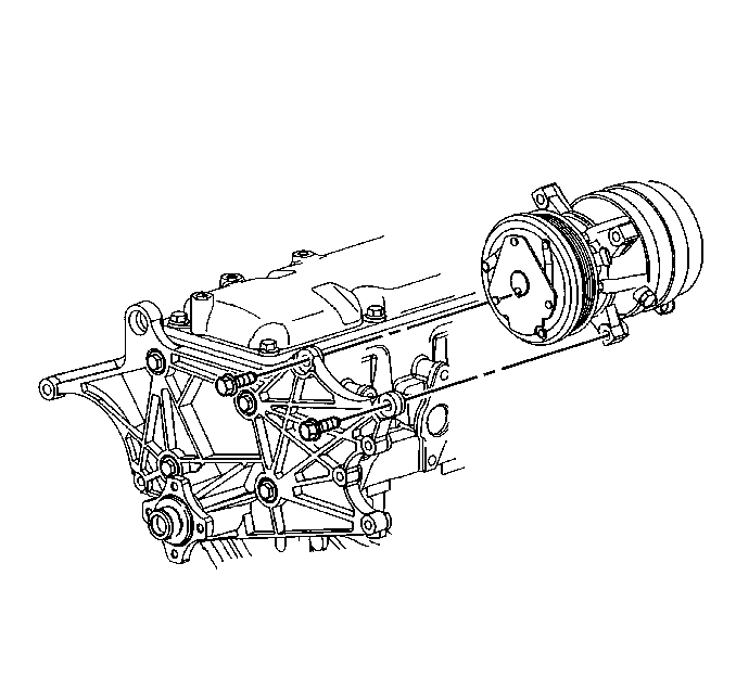
Important: Do not evacuate the air conditioning system.
Refer to Compressor Replacement in HVAC.
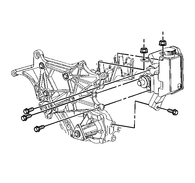
| 4.1. | Two nuts from the cylinder head studs |
| 4.2. | One bolt from the accessory bracket |
| 4.3. | Three bolts from the front of the power steering pump |
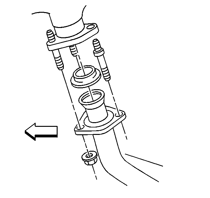
Refer to General Exhaust System Replacement .

Refer to Oil Level Indicator and Tube Replacement .
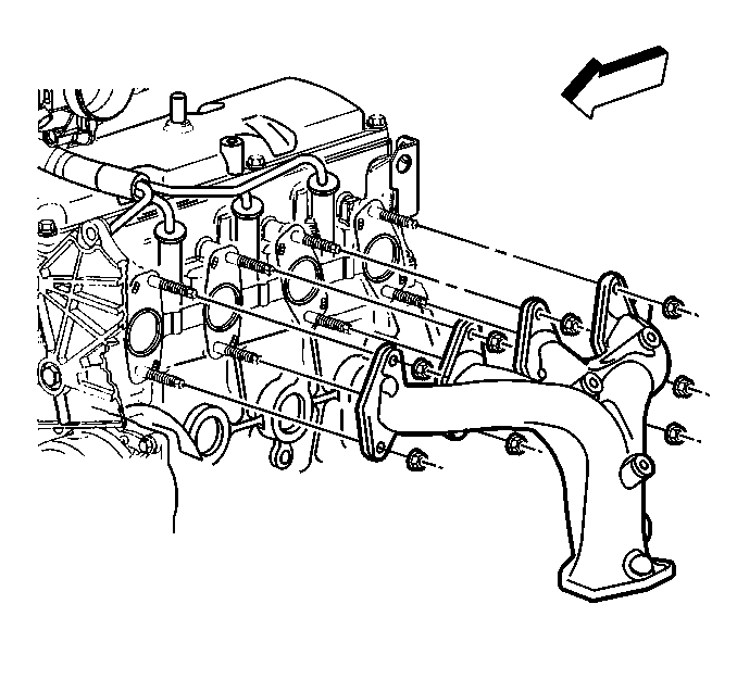
Refer to Exhaust Manifold Cleaning and Inspection .
Installation Procedure
- Install the exhaust manifold.
- Connect the oxygen sensor electrical connector.
- Install the oil level indicator tube.
- Install the exhaust pipe to the exhaust manifold.
- Install the power steering pump to the mounting bracket.
- Install the air conditioning compressor, if equipped.
- Install the drive belt.
- Connect the battery negative cable.

Refer to Exhaust Manifold Installation .

Refer to Oil Level Indicator and Tube Replacement .

Refer to General Exhaust System Replacement .

Tighten
Tighten the bolts and nuts in the following sequence:
| 5.1. | Tighten the three bolts to 30 N·m (22 lb ft) |
| 5.2. | Tighten the two nuts to 50 N·m (37 lb ft) |
| 5.3. | Tighten the lower bolt to 50 N·m (37 lb ft) |

Refer to Compressor Replacement in HVAC.

Refer to Drive Belt Replacement
