Notice: Use the correct fastener in the correct location. Replacement fasteners
must be the correct part number for that application. Fasteners requiring
replacement or fasteners requiring the use of thread locking compound or sealant
are identified in the service procedure. Do not use paints, lubricants, or
corrosion inhibitors on fasteners or fastener joint surfaces unless specified.
These coatings affect fastener torque and joint clamping force and may damage
the fastener. Use the correct tightening sequence and specifications when
installing fasteners in order to avoid damage to parts and systems.
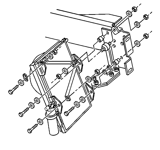
- Install the lower condenser brace to the condenser. Secure the brace
with the following components:
Tighten
Tighten the lower condenser brace nut to 70 N·m (51 lb ft).
- Install the upper condenser brace to the condenser. Secure the
brace with the following components:
Tighten
Tighten the upper condenser brace nut to 70 N·m (51 lb ft).
- Install the condenser insulator to the frame rail. Secure the
insulator with a washer and a nut.
Tighten
Tighten the condenser insulator nut to 35 N·m (26 lb ft).
- Install the condenser
to the frame rail. Secure the condenser with the following components:
| • | 2 condenser mounting bracket insulators |
Tighten
Tighten the condenser insulator bracket nuts to 24 N·m
(18 lb ft).
- Install the condenser brace insulator washer and the nut.
Tighten
Tighten the condenser insulator nut to 35 N·m (26 lb ft).
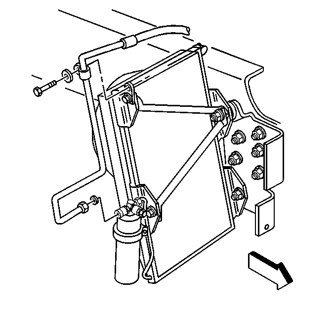
- Coat the new O-ring seal.
Use 525 viscosity refrigerant oil.
- Install the new O-ring seal.
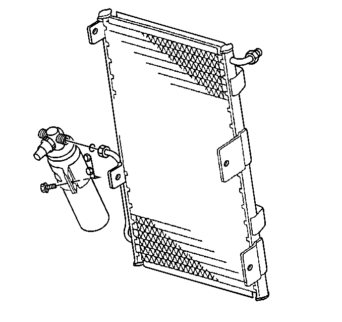
- Connect the condenser tube to the receiver dehydrator.
- Install the 2 clamp bracket screws.
- Coat the new O-ring seal with 525 viscosity refrigerant oil. Install
the new O-ring seal.
- Install the tube clamp
screw and washer to the top right corner of the condenser.
- Install the receiver dehydrator electrical connector to the receiver
dehydrator pressure switch.
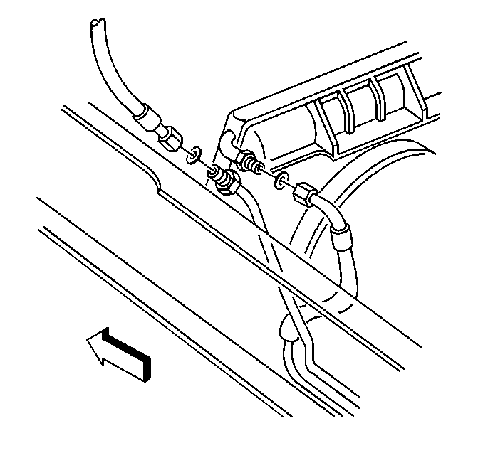
- Install the condenser hose to the condenser.
- Evacuate and recharge the A/C system. Refer to
Refrigerant Recovery and Recharging
.
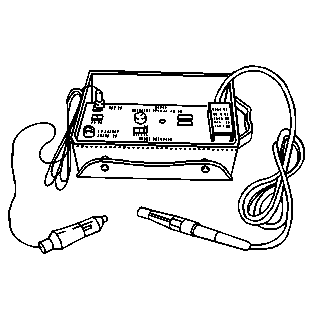
- Leak test the fitting(s) of the repaired or reinstalled component
using the J 39400-A
.
- Lower the cab. Refer to
Cab Tilting
in General Information.
