Data Link Communications Connector End Views w/o CTF
| Table 1: | Controller Area Network (CAN) Connector |
| Table 2: | Data Link Communications Resistor 1 |
| Table 3: | Data Link Communications Resistor 2 |
| Table 4: | Data Link Connector (DLC) |
| Table 5: | Serial Data Gateway (SDG) Module - JE4 or JE3 w/Allison® MD |
| Table 6: | Splice Pack SP203 |
| Table 7: | Splice Pack SP204 |
| Table 8: | Splice Pack SP205 |
| Table 9: | Splice Pack SP206 |
| Table 10: | Splice Pack SP207 |
| Table 11: | Splice Pack SP209 |
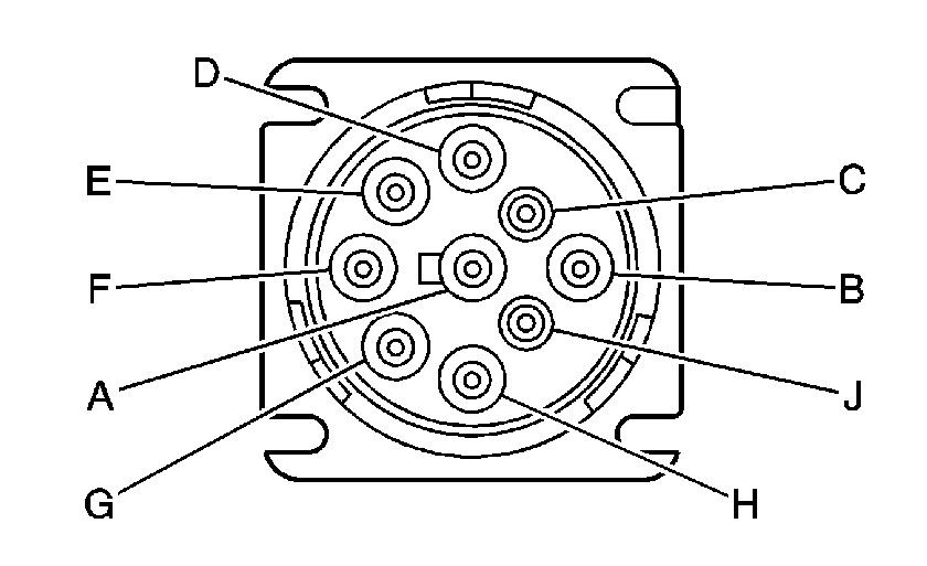
| |||||||
|---|---|---|---|---|---|---|---|
Connector Part Information |
| ||||||
Pin | Wire Color | Circuit No. | Function | ||||
A | BK | 437 | Ground | ||||
B | OG | 436 | Battery Positive Voltage | ||||
C | WH/D-BU | 373 | J1939 Serial Data High | ||||
D | BK/D-BU | 374 | J1939 Serial Data Low | ||||
E | -- | -- | Not Used | ||||
F | D-GN/WH | 490 | SAE J1708 Serial Data A | ||||
G | D-GN | 491 | SAE J1708 Serial Data B | ||||
H | BN | 503 | Ignition Sense (Allison® MD) | ||||
-- | -- | Not Used (All Others) | |||||
J | L-BU | 505 | Return | ||||

| |||||||
|---|---|---|---|---|---|---|---|
Connector Part Information |
| ||||||
Pin | Wire Color | Circuit No. | Function | ||||
A | BK | 112 | CAN Low | ||||
B | WH/RD | 111 | CAN High | ||||
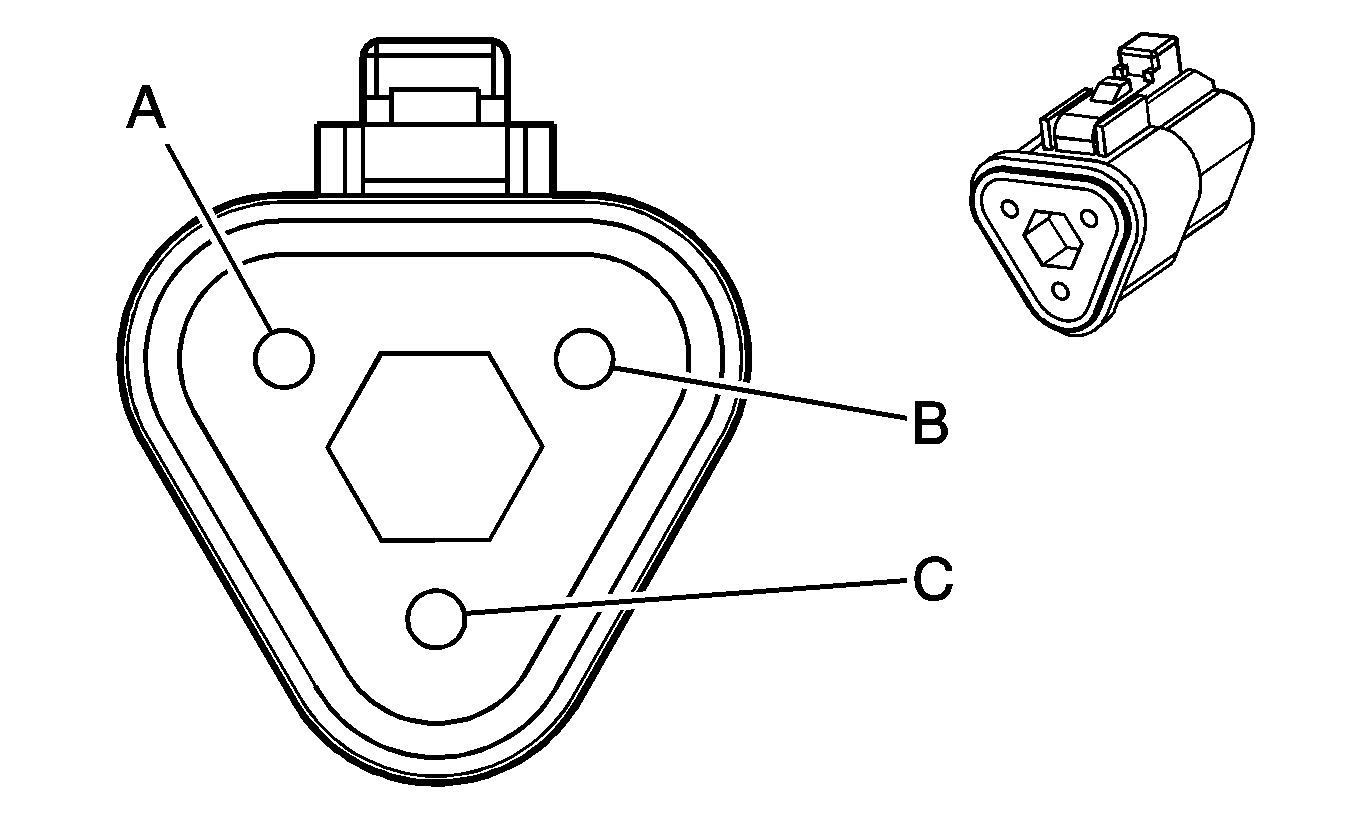
| |||||||
|---|---|---|---|---|---|---|---|
Connector Part Information |
| ||||||
Pin | Wire Color | Circuit No. | Function | ||||
A | BK/D-BU | 391 | CAN Low | ||||
B | WH/D-BU | 390 | CAN High | ||||
C | -- | -- | Not Used | ||||
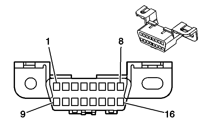
| |||||||
|---|---|---|---|---|---|---|---|
Connector Part Information |
| ||||||
Pin | Wire Color | Circuit No. | Function | ||||
1 | -- | -- | Not Used | ||||
2 | PU | 433 | SAE J1850 Serial Data | ||||
3 | -- | -- | Not Used | ||||
4 | BK | 434 | Ground | ||||
5 | BK/WH | 435 | Ground | ||||
6 | -- | -- | Not Used | ||||
7 | D-GN/WH | 492 | SAE J1708 Serial Data A | ||||
8-14 | -- | -- | Not Used | ||||
15 | D-GN | 493 | SAE J1708 Serial Data B | ||||
16 | OG | 432 | Battery Positive Voltage | ||||
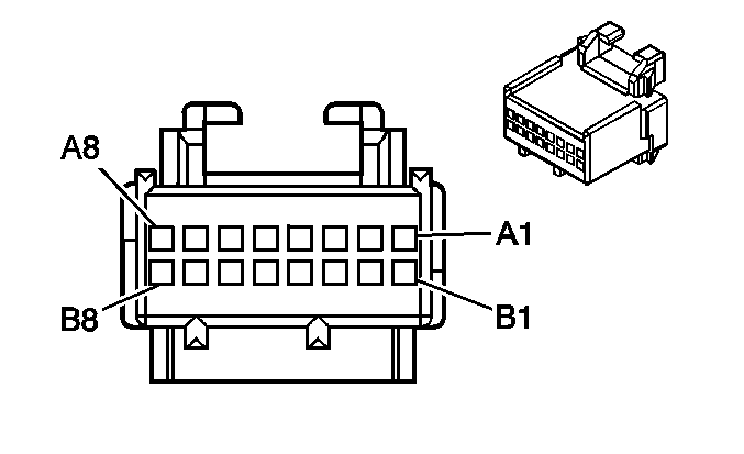
| |||||||
|---|---|---|---|---|---|---|---|
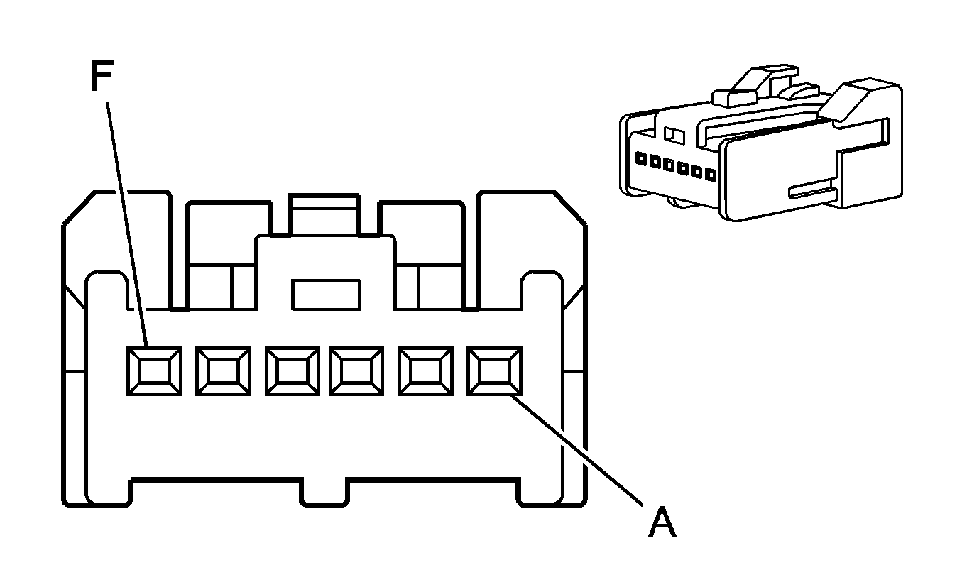
Connector Part Information |
| ||||||
Pin | Wire Color | Circuit No. | Function | ||||
A1 | BK/D-BU | 379 | J1939 Serial Data Low | ||||
A2 | WH/D-BU | 378 | J1939 Serial Data High | ||||
A3 | -- | -- | Not Used | ||||
A4 | BK/WH | 428 | Ground | ||||
A5 | -- | -- | Not Used | ||||
A6 | OG | 425 | Battery Positive Voltage | ||||
A7 | -- | -- | Not Used | ||||
A8 | RD/WH | 427 | Class 2 Serial Data | ||||
B1-B5 | -- | -- | Not Used | ||||
B6 | PK | 426 | Run/Start Voltage | ||||
B7-B8 | -- | -- | Not Used | ||||
| |||||||
|---|---|---|---|---|---|---|---|
Connector Part Information |
| ||||||
Pin | Wire Color | Circuit No. | Function | ||||
A | BK/D-BU | 374 | J1939 Serial Data Low | ||||
B | -- | -- | Not Used | ||||
C | BK/D-BU | 405 | J1939 Serial Data Low | ||||
D | WH/D-BU | 373 | J1939 Serial Data High | ||||
E | -- | -- | Not Used | ||||
F | WH/D-BU | 404 | J1939 Serial Data High | ||||

| |||||||
|---|---|---|---|---|---|---|---|
Connector Part Information |
| ||||||
Pin | Wire Color | Circuit No. | Function | ||||
A | BK/D-BU | 372 | J1939 Serial Data Low | ||||
B | BK/D-BU | 410 | J1939 Serial Data Low | ||||
C | BK/D-BU | 400 | J1939 Serial Data Low | ||||
D | WH/D-BU | 271 | J1939 Serial Data High | ||||
E | WH/D-BU | 409 | J1939 Serial Data High | ||||
F | WH/D-BU | 399 | J1939 Serial Data High | ||||
| |||||||
|---|---|---|---|---|---|---|---|
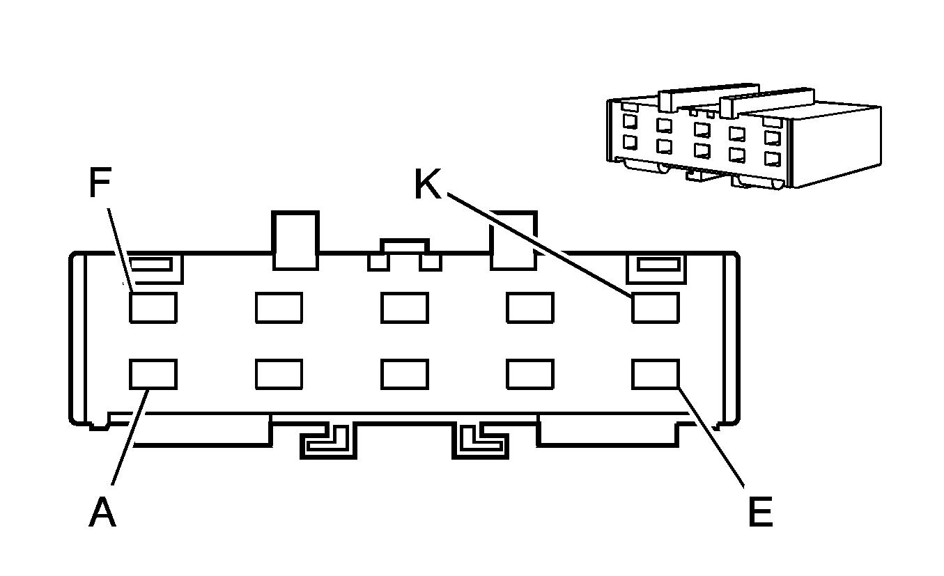
Connector Part Information |
| ||||||
Pin | Wire Color | Circuit No. | Function | ||||
A | D-GN | 493 | J1708 Serial Data B | ||||
B | D-GN | 491 | J1708 Serial Data B | ||||
C | -- | -- | Not Used | ||||
D | D-GN/WH | 492 | J1708 Serial Data A | ||||
E | D-GN/WH | 490 | J1708 Serial Data A | ||||
F | D-GN | 613 | J1708 Serial Data B (JE4) | ||||
-- | -- | Not Used (JE3) | |||||
G | D-GN | 502 | J1708 Serial Data B (Allison® MD) | ||||
-- | -- | Not Used (All Others) | |||||
H | -- | -- | Not Used | ||||
J | D-GN/WH | 612 | J1708 Serial Data A (JE4) | ||||
-- | -- | Not Used (JE3) | |||||
K | D-GN/WH | 501 | J1708 Serial Data A (Allison® MD) | ||||
-- | -- | Not Used (All Others) | |||||
| |||||||
|---|---|---|---|---|---|---|---|
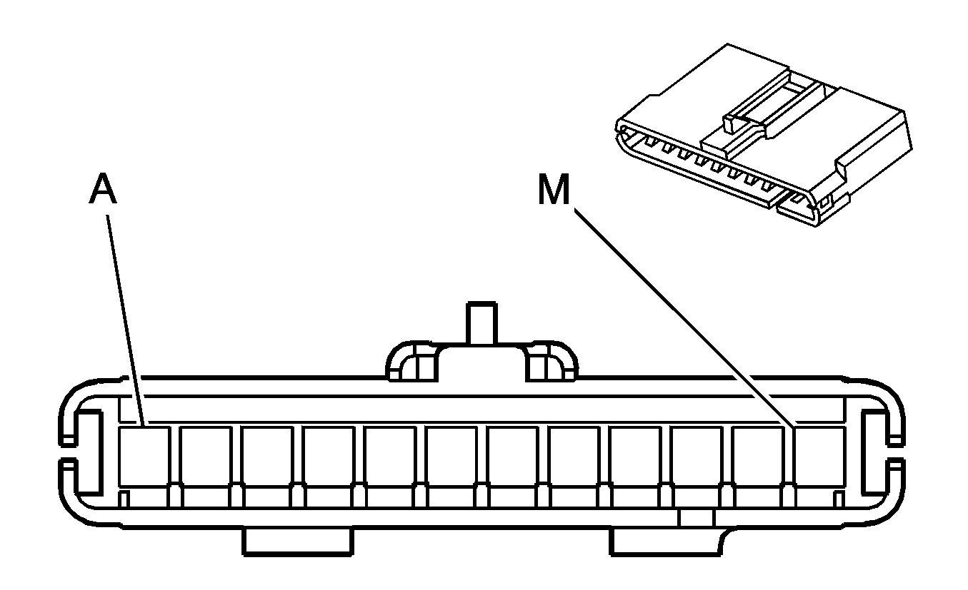
Connector Part Information |
| ||||||
Pin | Wire Color | Circuit No. | Function | ||||
A | PU | 433 | DLC Class 2 Serial Data | ||||
B | D-GN | 274 | ECM/PCM/VCM Class 2 Serial Data | ||||
C | RD/WH | 427 | Class 2 Serial Data (JE4 or JE3 w/Allison® MD) | ||||
-- | -- | Not Used (All Others) | |||||
D | -- | -- | Not Used | ||||
E | L-BU | 472 | ABS/TCS Class 2 Serial Data (JE3) | ||||
-- | -- | Not Used (JE4) | |||||
F | -- | -- | Not Used | ||||
G | GY | 367 | IPC Class 2 Serial Data | ||||
H-J | -- | -- | Not Used | ||||
K | YE | 669 | J1850 Class 2 Serial Data (Allison® LCT) | ||||
-- | -- | Not Used (All Others) | |||||
L | -- | -- | Not Used | ||||
M | D-BU/WH | 430 | Chime Module Bit 1 Signal | ||||

| |||||||
|---|---|---|---|---|---|---|---|
Connector Part Information |
| ||||||
Pin | Wire Color | Circuit No. | Function | ||||
A | BK/D-BU | 400 | J1939 Serial Data Low | ||||
B | BK/D-BU | 395 | J1939 Serial Data Low | ||||
C | -- | -- | Not Used | ||||
D | WH/D-BU | 399 | J1939 Serial Data High | ||||
E | WH/D-BU | 394 | J1939 Serial Data High | ||||
F | BK/D-BU | 671 | J1939 Serial Data Low (Allison® LCT) | ||||
519 | J1939 Serial Data Low (Allison® MD) | ||||||
-- | -- | Not Used (All Others) | |||||
G | BK/D-BU | 405 | J1939 Serial Data Low | ||||
H | -- | -- | Not Used | ||||
J | WH/D-BU | 404 | J1939 Serial Data High | ||||
K | WH/D-BU | 670 | J1939 Serial Data High (Allison® LCT) | ||||
518 | J1939 Serial Data High (Allison® MD) | ||||||
-- | -- | Not Used (All Others) | |||||

| |||||||
|---|---|---|---|---|---|---|---|
Connector Part Information |
| ||||||
Pin | Wire Color | Circuit No. | Function | ||||
A | BK/D-BU | 379 | J1939 Serial Data Low (JE4 or JE3 w/Allison® MD) | ||||
-- | -- | Not Used (All Others) | |||||
B | BK/D-BU | 395 | J1939 Serial Data Low | ||||
C | BK/D-BU | 391 | J1939 Serial Data Low | ||||
D | WH/D-BU | 378 | J1939 Serial Data High (JE4 or JE3 w/Allison® MD) | ||||
-- | -- | Not Used (All Others) | |||||
E | WH/D-BU | 394 | J1939 Serial Data High | ||||
F | WH/D-BU | 390 | J1939 Serial Data High | ||||
Data Link Communications Connector End Views CTF
| Table 1: | Controller Area Network (CAN) Connector |
| Table 2: | Data Link Communications Resistor 1 |
| Table 3: | Data Link Communications Resistor 2 |
| Table 4: | Data Link Connector (DLC) |
| Table 5: | Serial Data Gateway (SDG) Module - JE4 or JE3 w/Allison® MD |
| Table 6: | Splice Pack SP205 |
| Table 7: | Splice Pack SP206 |
| Table 8: | Splice Pack SP209 |
| Table 9: | Splice Pack SP219 |
| Table 10: | Splice Pack SP230 |
| Table 11: | Splice Pack SP231 |

| |||||||
|---|---|---|---|---|---|---|---|
Connector Part Information |
| ||||||
Pin | Wire Color | Circuit No. | Function | ||||
A | BK | HU04 | Ground | ||||
B | OG | HF10 | Battery Positive Voltage | ||||
C | D-BU | HF21 | J1939 Serial Data High | ||||
D | BK/WH | HF22 | J1939 Serial Data Low | ||||
E | -- | -- | Not Used | ||||
F | D-GN/WH | HF11 | SAE J1708 Serial Data A | ||||
G | D-GN | HF12 | SAE J1708 Serial Data B | ||||
H | -- | -- | Not Used | ||||
J | L-BU | NF09 | Return | ||||

| |||||||
|---|---|---|---|---|---|---|---|
Connector Part Information |
| ||||||
Pin | Wire Color | Circuit No. | Function | ||||
A | L-GN/RD | TF08 | CAN Low | ||||
B | WH/RD | TF07 | CAN High | ||||
C | -- | -- | Not Used | ||||

| |||||||
|---|---|---|---|---|---|---|---|
Connector Part Information |
| ||||||
Pin | Wire Color | Circuit No. | Function | ||||
A | BK/WH | TF02 | CAN Low | ||||
B | D-BU | TF01 | CAN High | ||||

| |||||||
|---|---|---|---|---|---|---|---|
Connector Part Information |
| ||||||
Pin | Wire Color | Circuit No. | Function | ||||
1 | -- | -- | Not Used | ||||
2 | PU | HF09 | SAE J1850 Serial Data | ||||
3 | -- | -- | Not Used | ||||
4 | BK | HU02 | Ground | ||||
5 | BK/WH | HU03 | Ground | ||||
6 | -- | -- | Not Used | ||||
7 | D-GN/WH | HF07 | SAE J1708 Serial Data A (JE4 and Allison® MD) | ||||
8-14 | -- | -- | Not Used | ||||
15 | D-GN | HF08 | SAE J1708 Serial Data B | ||||
16 | OG | HF06 | Battery Positive Voltage | ||||

| |||||||
|---|---|---|---|---|---|---|---|
Connector Part Information |
| ||||||
Pin | Wire Color | Circuit No. | Function | ||||
A1 | BK/WH | HF18 | J1939 Serial Data Low | ||||
A2 | D-BU | HF17 | J1939 Serial Data High | ||||
A3 | -- | -- | Not Used | ||||
A4 | BK/WH | HU01 | Ground | ||||
A5 | -- | -- | Not Used | ||||
A6 | OG | HF01 | Battery Positive Voltage | ||||
A7 | -- | -- | Not Used | ||||
A8 | RD/WH | HF05 | Class 2 Serial Data | ||||
B1-B5 | -- | -- | Not Used | ||||
B6 | PK | HF02 | Run/Start Voltage | ||||
B7-B8 | -- | -- | Not Used | ||||

| |||||||
|---|---|---|---|---|---|---|---|
Connector Part Information |
| ||||||
Pin | Wire Color | Circuit No. | Function | ||||
A | D-GN | HF08 | J1708 Serial Data B | ||||
B | D-GN | HF12 | J1708 Serial Data B | ||||
C | -- | -- | Not Used | ||||
D | D-GN/WH | HF07 | J1708 Serial Data A | ||||
E | D-GN/WH | HF11 | J1708 Serial Data A | ||||
F | D-GN | BB17 | J1708 Serial Data B | ||||
G | D-GN | NF08 | J1708 Serial Data B | ||||
H | -- | -- | Not Used | ||||
J | D-GN/WH | BB16 | J1708 Serial Data A | ||||
K | D-GN/WH | NF08 | J1708 Serial Data A | ||||

| |||||||
|---|---|---|---|---|---|---|---|
Connector Part Information |
| ||||||
Pin | Wire Color | Circuit No. | Function | ||||
A | PU | HF09 | DLC Class 2 Serial Data | ||||
B | D-GN | CF34 | ECM/PCM/VCM Class 2 Serial Data | ||||
C | RD/WH | HF05 | Class 2 Serial Data | ||||
D | -- | -- | Not Used | ||||
E | L-BU | BG04 | ABS/TCS Class 2 Serial Data (JE3) | ||||
-- | -- | Not Used (JE4) | |||||
F | -- | -- | Not Used | ||||
G | GY | MA04 | IPC Class 2 Serial Data | ||||
H-J | -- | -- | Not Used | ||||
K | YE | OA57 | J1850 Class 2 Serial Data (Allison® LCT) | ||||
-- | -- | Not Used (All Others) | |||||
L | -- | -- | Not Used | ||||
M | D-BU/WH | HF16 | Chime Module Bit 1 Signal | ||||

| |||||||
|---|---|---|---|---|---|---|---|
Connector Part Information |
| ||||||
Pin | Wire Color | Circuit No. | Function | ||||
A | BK/WH | HF18 | CAN Low | ||||
B | BK/WH | TF04 | CAN Low | ||||
C | BK/WH | TF02 | CAN Low | ||||
D | D-BU | HF17 | CAN High | ||||
E | D-BU | TF03 | CAN High | ||||
F | D-BU | TF01 | CAN High | ||||

| |||||||
|---|---|---|---|---|---|---|---|
Connector Part Information |
| ||||||
Pin | Wire Color | Circuit No. | Function | ||||
A | GY/D-BU | TF06 | Shield | ||||
B | GY/D-BU | HF20 | Shield | ||||
C-F | -- | -- | Not Used | ||||

| |||||||
|---|---|---|---|---|---|---|---|
Connector Part Information |
| ||||||
Pin | Wire Color | Circuit No. | Function | ||||
A | BK/WH | OA61 | CAN Low (Allison® LCT) | ||||
BK/WH | NF64 | CAN Low (Allison® MD) | |||||
B | BK/WH | TF09 | CAN Low | ||||
C | BK/WH | TF04 | CAN Low | ||||
D | D-BU | OA60 | CAN High (Allison® LCT) | ||||
D-BU | NF63 | CAN High (Allison® MD) | |||||
E | D-BU | TF08 | CAN High | ||||
F | D-BU | TF03 | CAN High | ||||

| |||||||
|---|---|---|---|---|---|---|---|
Connector Part Information |
| ||||||
Pin | Wire Color | Circuit No. | Function | ||||
A | GY/D-BU | TF06 | Shield | ||||
B | GY/D-BU | TF11 | Shield | ||||
C | GY/D-BU | OA63 | Shield (Allison® LCT) | ||||
GY/D-BU | NF66 | Shield (Allison® MD) | |||||
D-F | -- | -- | Not Used | ||||
