Special Tools
| • | EN-48243 Engine Assembly Remove/Install Pallet |
| • |
EN-48244 Engine Assembly Remove/Install Pallet Supporter |
Removal Procedure
- Discharge the air conditioning (A/C) system, if equipped.
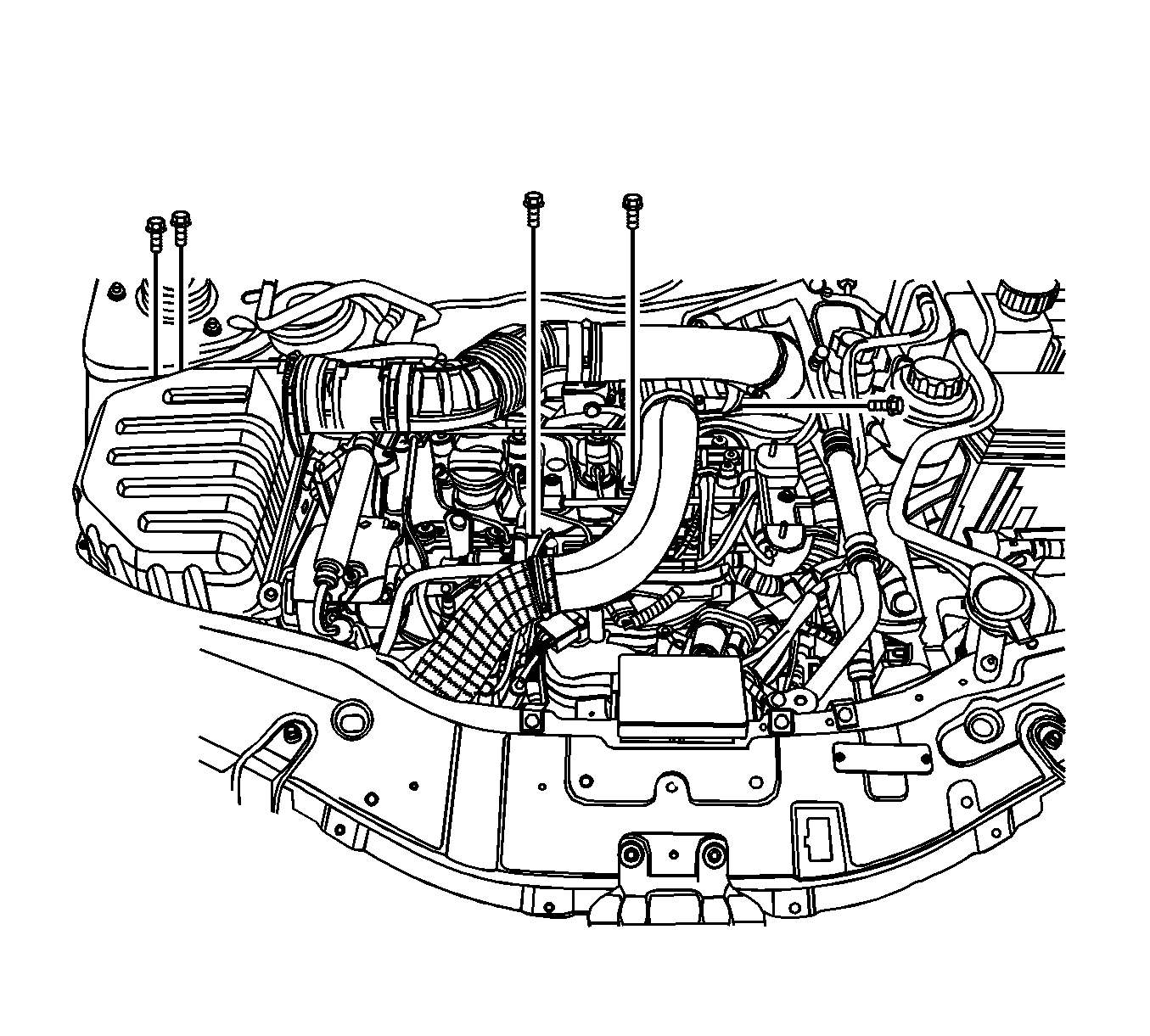
- Drain the power steering oil, if equipped.
- Disconnect the negative battery cable.
- Remove the engine cover. Refer to
Engine Cover Replacement.
- Remove the charge air system hoses and ducts. Refer to
Charge Air Cooler Inlet Pipe and Outlet Pipe Replacement.
- Drain the engine coolant. Refer to
Cooling System Draining and Filling.

- Disconnect the fuel feeding pipe connector (a).
- Disconnect the coolant hose from the surge tank (b, c).
- Disconnect the fuel return hose from the junction block (d).

- Disconnect the engine wiring harness as follows:
| • | Disconnect the fuel heater wiring connector (a). |
| • | Disconnect the mass air flow sensor (MAF) connector (b). |
| • | Disconnect the exhaust temperature sensor wiring connector (c). |
| • | Disconnect the DPF pressure sensor connector (d). |
| • | Disconnect the engine oil pressure switch connector (e). |
| • | Disconnect the common rail pressure sensor connector (f). |
| • | Disconnect the coolant temperature sensor connector (g). |
| • | Disconnect the EGR vacuum solenoid connector (h). |
| • | Disconnect the fuel injector connector (i). |
| • | Disconnect the camshaft position sensor (CMP) connector (j). |
| • | Disconnect the turbocharger actuator connector (k). |
| • | Disconnect the glow plug wire connector (l). |
| • | Disconnect the booster pressure (T-MAP) sensor connector (m) |
| • | Disconnect the common rail regulator connector (n). |
| • | Disconnect the ETC body connector (o). |
| • | Disconnect the fuel injection pump connector (p). |
| • | Disconnect the cooling fan connectors (q). |
| • | Disconnect the A/C compressor connector (r). |
| • | Disconnect the starter solenoid wiring connector (s). |
| • | Disconnect the A/C pressure sensor connector (t). |
| • | Disconnect the transaxle range (TR) switch connector, if auto-transaxle (u). |
| • | Disconnect the transaxle wiring electrical connector, if auto-transaxle (v). |
| • | Disconnect the input speed sensor electrical connector, if auto-transaxle (w). |
| • | Disconnect the output speed sensor electrical connector, if auto-transaxle (x). |
| • | Disconnect the speed sensor connector, if manual-transaxle (y). |
| • | Disconnect the crankshaft position sensor (z). |
| • | Disconnect the generator connector (B). |

- Remove the engine hardware and components as follows:
| 11.1. | Remove the engine splice pack tighten bolt from the intake manifold (1). |
| 11.2. | Remove the glow plug module (2). |
| 11.3. | Remove the glow plug fuse box (3). |
| 11.4. | Remove the generator B+ connector nut (4). |
| 11.5. | Remove the starter solenoid connector nut (5). |
| 11.6. | Remove the engine ground bolt (6). |

- Remove the surge tank. Refer to
Radiator Surge Tank Replacement.
- Remove the power steering pump pipes from the power steering pump.
- Remove the front drive axle shafts. Refer to
Front Wheel Drive Shaft Replacement.
- Remove the steering intermediate shaft lower pinch bolt.
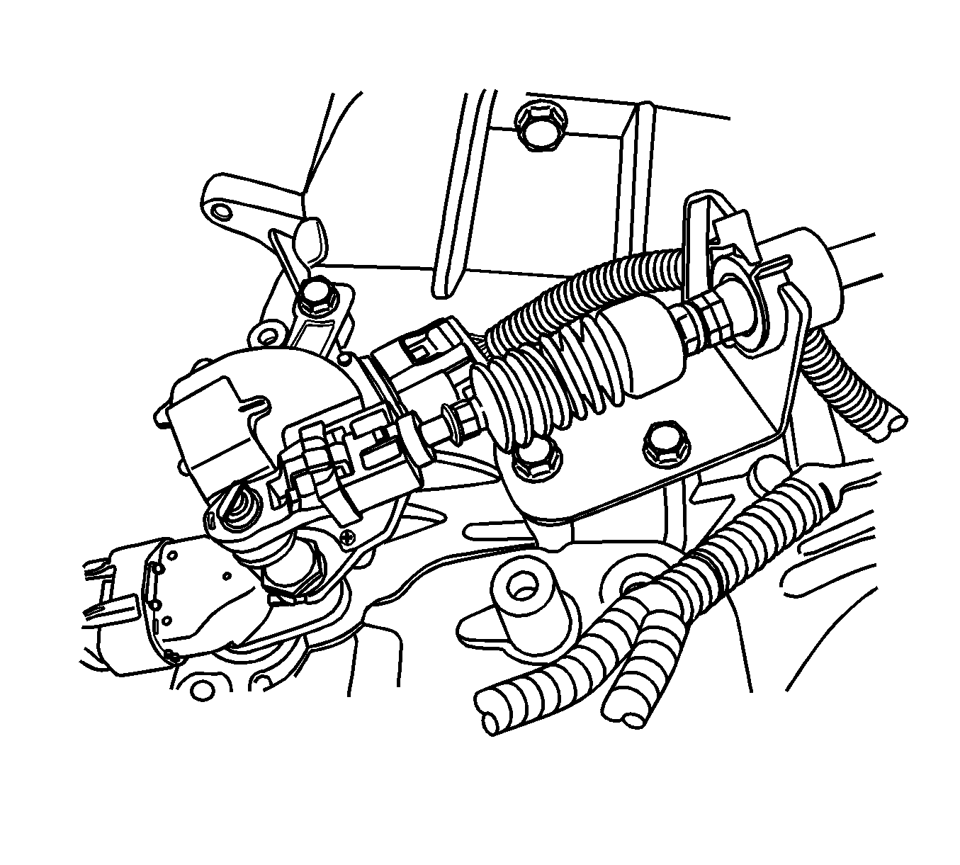
- For automatic transaxle, remove the shift control cable from the automatic transaxle. Refer to
Shift Control Cable Replacement.
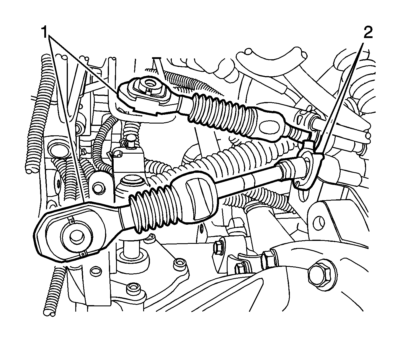
- For manual transaxle, remove the select cable from the transaxle. Refer to
Transmission Control Replacement.
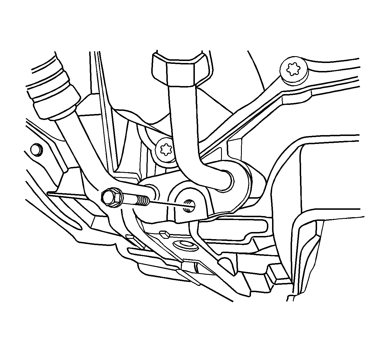
- For automatic transaxle, remove the transaxle oil cooler hoses from the auto-transaxle.
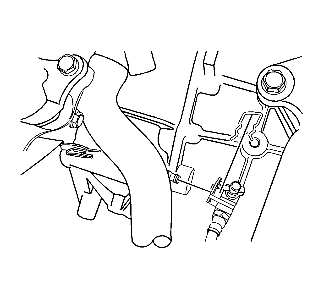
- For manual transaxle, remove the clutch actuator cylinder pipe from the transaxle. Refer to
Clutch Concentric Actuator Cylinder Replacement.
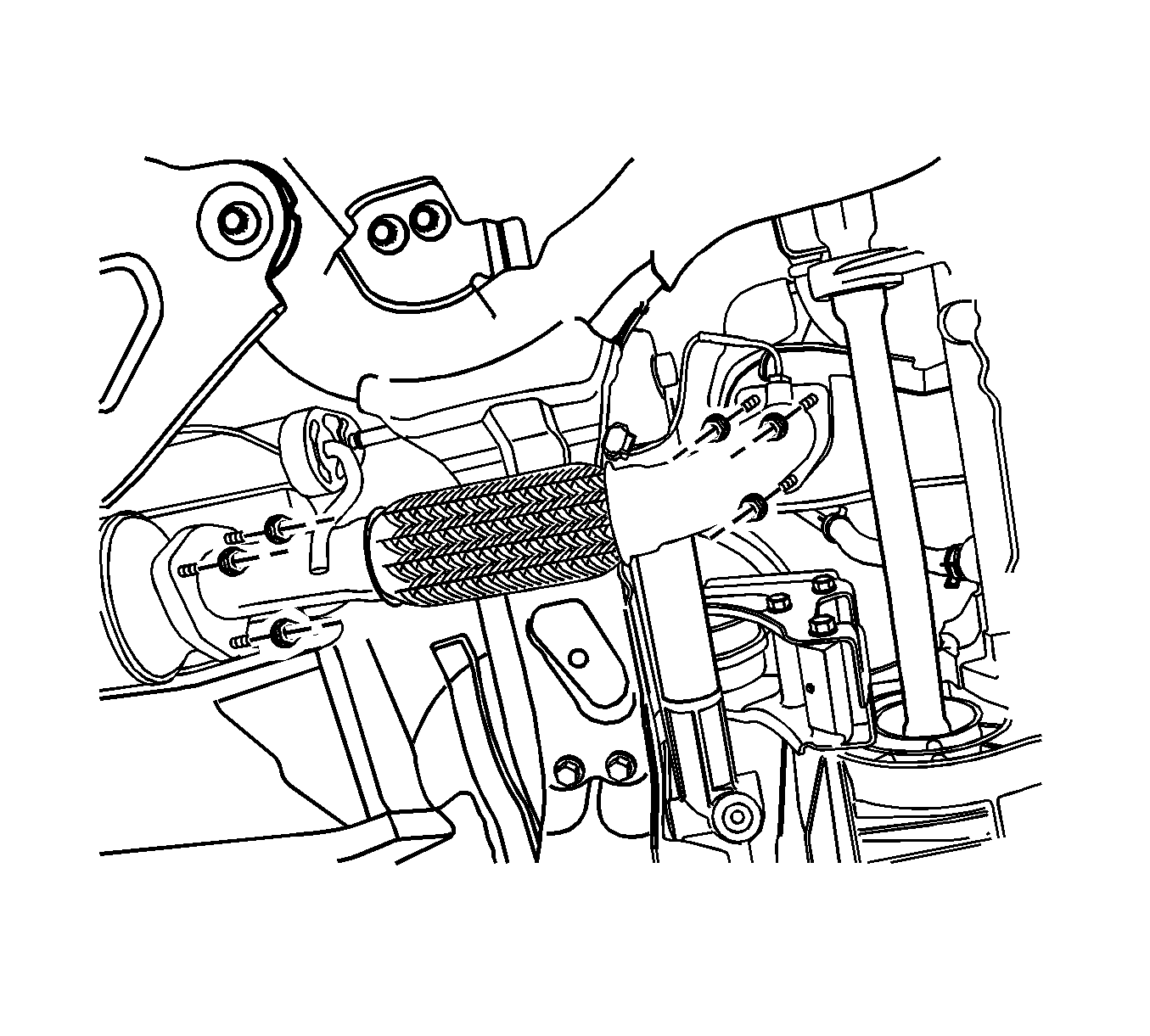
- Remove the front exhaust pipe between the pre-catalyst and the diesel particulate filter pipe.

- Remove the A/C compressor pipe from the compressor.
- Remove the power steering return cooling pipe.
- Remove the propeller shaft assembly from the transfer case, if equipped. Refer to
Propeller Shaft Replacement.

- Remove the cradle supporter bracket.
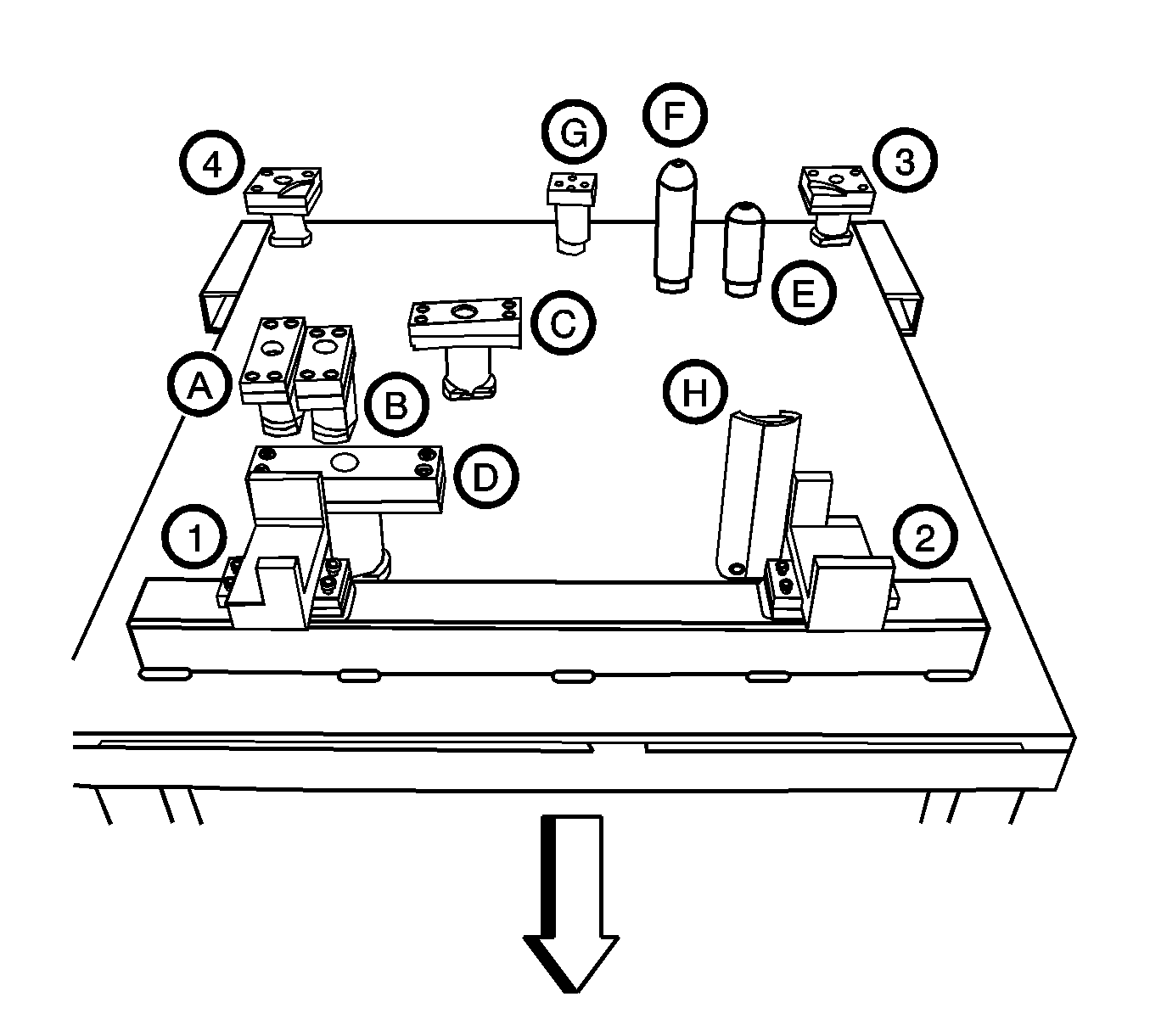
Note: Make sure all components are set on the exact position of the
EN-48243 pallet
with
EN-48244 supporter
.
- Remove the cradle tightening bolts.
| • | Diesel Engine Oil Pan Supporter |
| • | FAM II 2.4L Diesel Engine Oil Pan Supporter |
| • | HFV6 3.2L Engine Oil Pan Supporter |
| • | Manual Transaxle Supporter |
| • | Automatic Transaxle Supporter |
| • | Transfer Case Supporter (M/T & A/T) |
| • | Transaxle Mount Supporter (M/T & A/T) |

Note: Only lower the vehicle far enough to take the weight off the engine and transaxle mount, or damage to the mount and pallet/pallet supporter failure may occur.
- Lower the vehicle and position the engine assembly on to the
EN-48243 pallet
with the
EN-48244 supporter
to
the cradle.
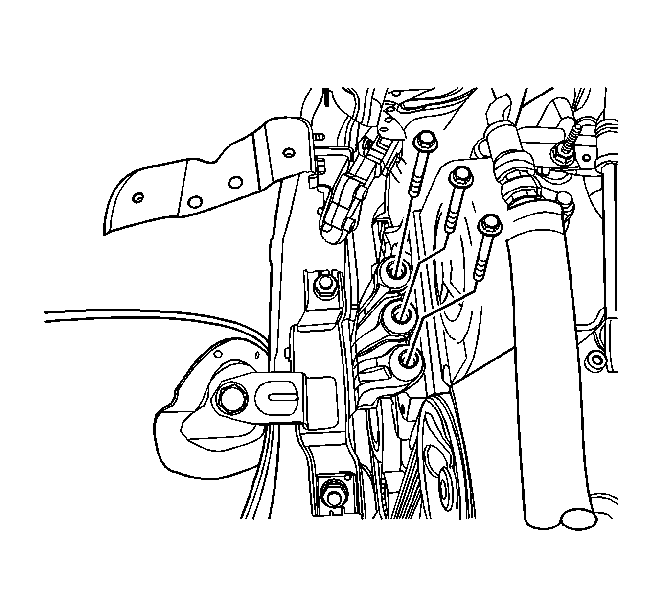
- Remove the engine mount bolt from the engine mount bracket.

- Remove the transaxle mount bolt from the transaxle.

- Tighten the engine assembly using by hoist, etc.
- Remove the transaxle front mount.

- Remove the transaxle rear mount.
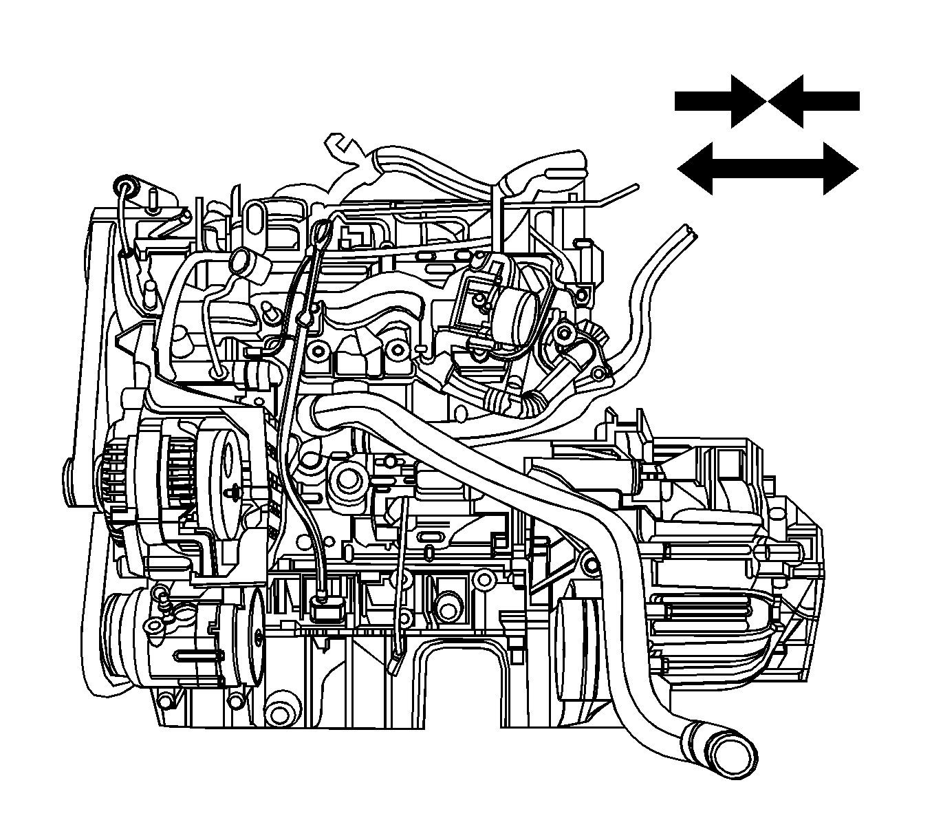
- Remove the engine and transaxle.
Installation Procedure
Caution: Refer to Fastener Caution in the Preface section.

- Install the transaxle to engine assembly and tighten.
| • | The transaxle tightening bolts to 75 N·m (55.3 lb ft). |
| • | The oil pan flange-to-transaxle bolts to 50 N·m (36.9 lb ft). |
Note: Make sure all the components are set on the exact position on the
EN-48243 Engine Assembly Remove/Install Pallet
with EN-48244.
- Install the cradle on the
EN-48243 pallet
with the
EN-48244 supporter
and then assemble the engine and the
transaxle onto the cradle.

- Lower the vehicle and position the engine and transaxle assembly with the cradle attached on to the
EN-48243
with the
EN-48244 supporter
to the vehicle.

- Install the transaxle rear mount and tighten the bolt to
90 N·m (66.4 lb ft).

- Install the transaxle front mount and tighten the bolt to
90 N·m (66.4 lb ft).

- Install the transaxle mount and tighten.
| • | The transaxle mount assembly retaining bolts (2) to 37 N·m (27 lb ft). |
| • | The transaxle mount bracket retaining bolts (1) to 50 N·m (37 lb ft). |

- Install the engine mount bolt and tighten the retaining bolts to
50 N·m (37 lb ft).

- Remove the
EN-48243 pallet
with the
EN-48244 supporter
from the vehicle.
- Install the cradle to body mounting bolts and tighten to
155 N·m (114.3 lb ft).
- Install the cradle support bracket retaining bolts and tighten to
50 N·m (36.9 lb ft).

- Connect the engine wiring harness.
| • | Connect the fuel heater wiring connector (a). |
| • | Connect the mass air flow sensor (MAF) connector (b). |
| • | Connect the exhaust temperature sensor wiring connector (c). |
| • | Connect the DPF pressure sensor connector (d). |
| • | Connect the engine oil pressure switch connector (e). |
| • | Connect the common rail pressure sensor connector (f). |
| • | Connect the coolant temperature sensor connector (g). |
| • | Connect the EGR vacuum solenoid connector (h). |
| • | Connect the fuel injector connector (i). |
| • | Connect the camshaft position sensor (CMP) connector (j). |
| • | Connect the turbocharger actuator connector (k). |
| • | Connect the glow plug wire connector (l). |
| • | Connect the booster pressure (T-MAP) sensor connector (m) |
| • | Connect the common rail regulator connector (n). |
| • | Connect the ETC body connector (o). |
| • | Connect the fuel injection pump connector (p). |
| • | Connect the cooling fan connectors (q). |
| • | Connect the A/C compressor connector (r). |
| • | Connect the starter solenoid wiring connector (s). |
| • | Connect the A/C pressure sensor connector (t). |
| • | Connect the transaxle range (TR) switch connector, if auto-transaxle (u). |
| • | Connect the transaxle wiring electrical connector, if auto-transaxle (v). |
| • | Connect the input speed sensor electrical connector, if auto-transaxle (w). |
| • | Connect the output speed sensor electrical connector, if auto-transaxle (x). |
| • | Connect the speed sensor connector, if manual-transaxle (y). |
| • | Connect the crankshaft position sensor (z). |
| • | Connect the generator connector (B). |
- Install the engine hardware and components as follows:
| 12.1. | Install the engine splice pack tighten bolt from the intake manifold (1) and tighten the bolt to
15 N·m (11.1 lb ft). |
| 12.2. | Install the glow plug module (2) and tighten the retaining nut to
14 N·m (10.3 lb ft). |
| 12.3. | Install the glow plug fuse box (3) and tighten the bolts to
10 N·m (88.5 lb in). |
| 12.4. | Install the generator B+ connector nut (4) and tighten to
25 N·m (18.4 lb ft). |
| 12.5. | Install the starter solenoid connector nut (5) and tighten to
15 N·m (11.1 lb ft). |
| 12.6. | Install the engine ground bolt (6) and tighten to
25 N·m (18.4 lb ft). |


