- Lubricate the valve rocker arms and pushrods with clean engine oil.
- Lubricate the flange of the valve rocker arm bolts with clean engine oil.
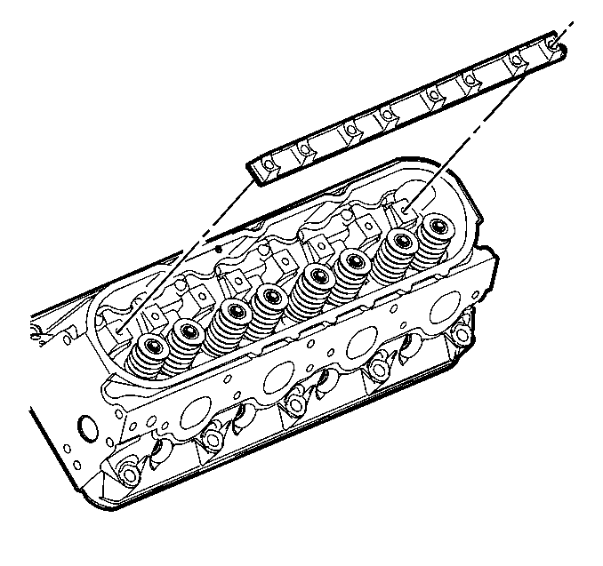
- Install the valve rocker arm pivot support.
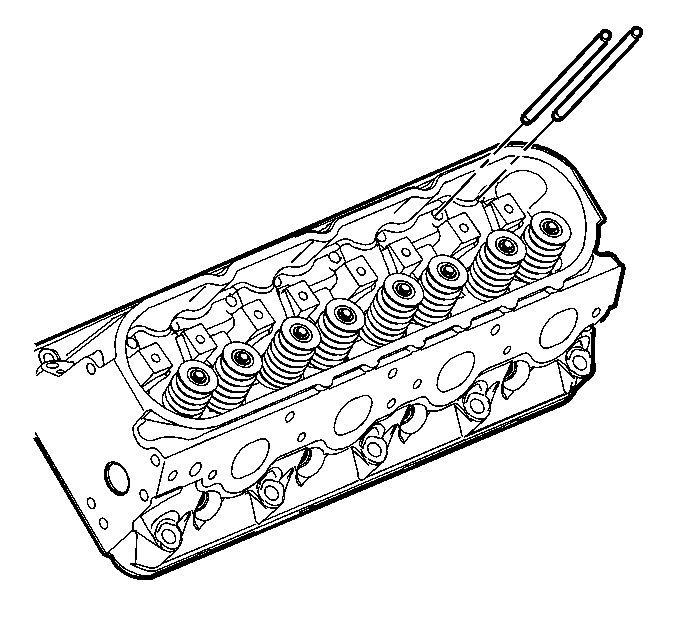
- Install the pushrods.
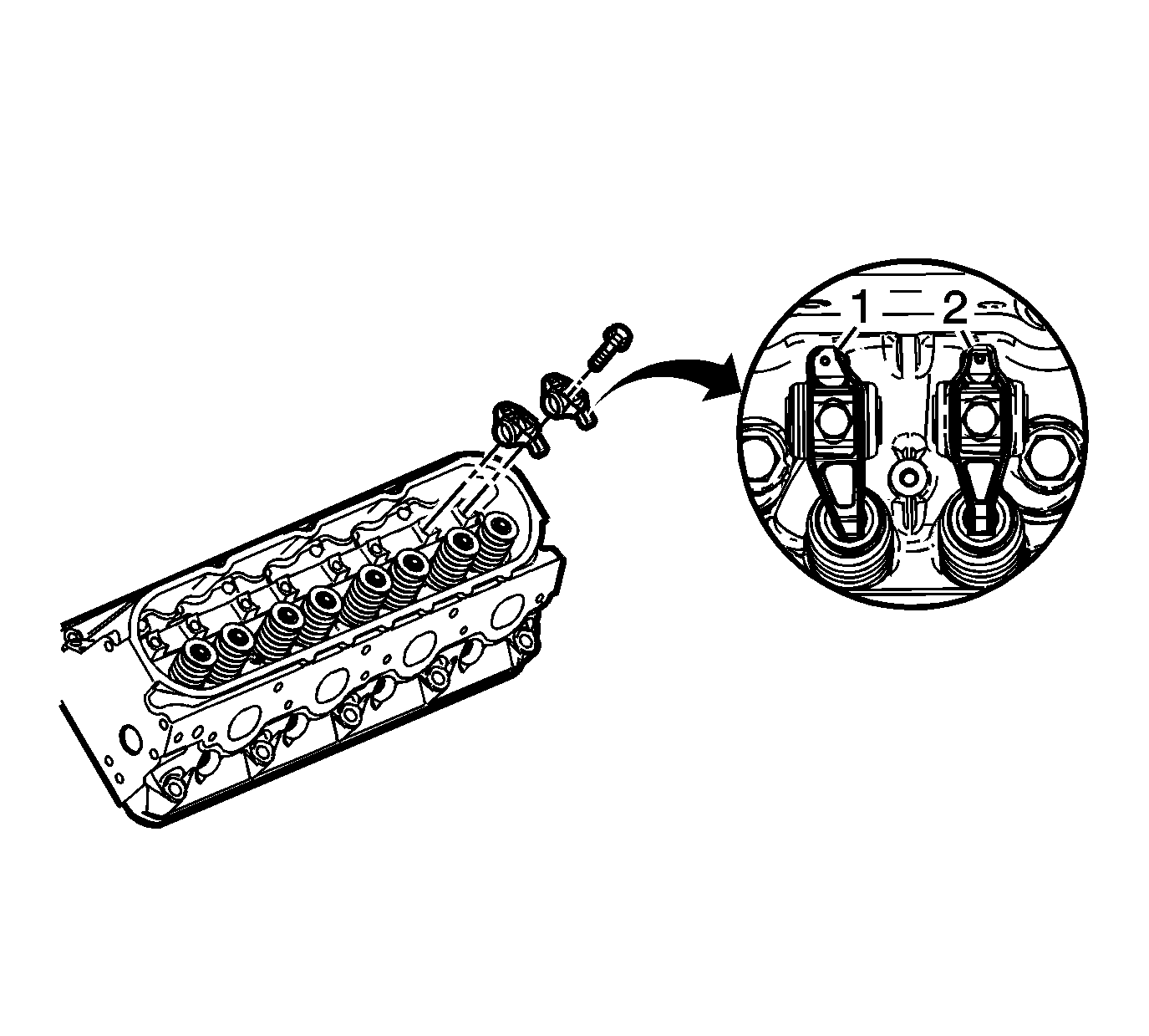
- Install the rocker arms and bolts.
- Rotate the crankshaft until number 1 piston is at top dead center of compression stroke.
- With the engine in the number 1 firing position, tighten the following valve rocker arm bolts:
- Rotate the crankshaft 360 degrees.
- Tighten the following valve rocker arm bolts:

Note:
• When using the valve train components again, always install the components to the original location and position. • Valve lash is net build. No valve adjustment is required.

Note: Ensure the pushrods seat properly to the valve lifter sockets.

Note:
• Ensure the pushrods seat properly to the ends of the rocker arms. • DO NOT tighten the rocker arm bolts at this time.
The intake rocker arms (1) have an offset design.

In this position, cylinder number 1 rocker arms will be off lobe lift, and the crankshaft sprocket key will be at the 1:30 position. The camshaft and crankshaft sprocket alignment marks (1, 2) will be in the 12 o'clock position. If viewing from the rear of the engine, the additional crankshaft pilot hole, non-threaded, will be in the 10:30 position.
The engine firing order is 1, 8, 7, 2, 6, 5, 4, 3.
Cylinders 1, 3, 5 and 7 are left bank.
Cylinders 2, 4, 6, and 8 are right bank.
Caution: Refer to Fastener Caution in the Preface section.
| 7.1. | Tighten the exhaust valve rocker arm bolts 1, 2, 7, and 8 to 30 N·m (22 lb ft). |
| 7.2. | Tighten the intake valve rocker arm bolts 1, 3, 4, and 5 to 30 N·m (22 lb ft). |
| 9.1. | Tighten the exhaust valve rocker arm bolts 3, 4, 5, and 6 to 30 N·m (22 lb ft). |
| 9.2. | Tighten the intake valve rocker arm bolts 2, 6, 7, and 8 to 30 N·m (22 lb ft). |
