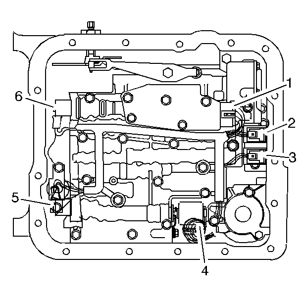
- Remove all electrical connectors (1-6) from the electrical components.
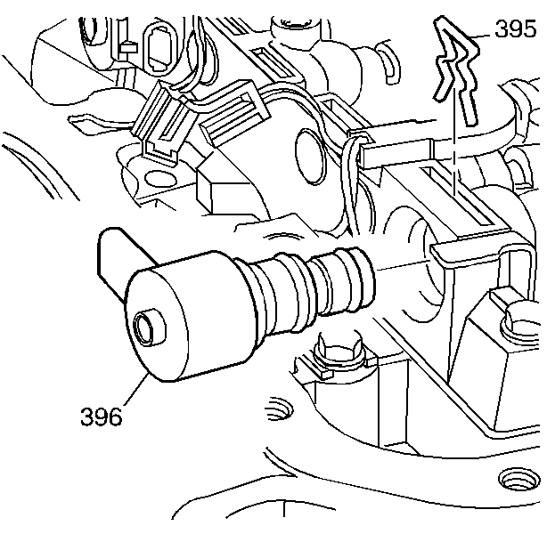
- Remove the TCC PWM retainer clip (395).
- Remove the TCC PWM solenoid (396).
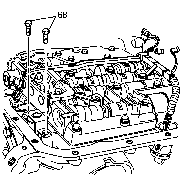
- Remove the TCC solenoid bolts (68).
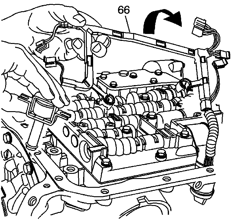
- Remove the TCC solenoid and wiring harness (66). Turn the wiring harness over so that it hangs over the side of the transmission.
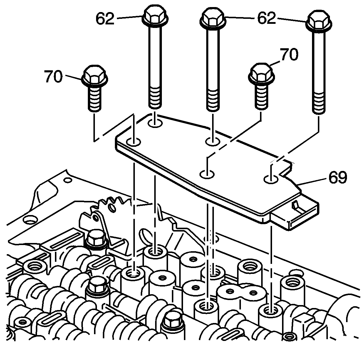
- Remove the transmission fluid pressure (TFP) manual valve position switch assembly bolts (62, 70).
- Remove the TFP manual valve position switch (69).
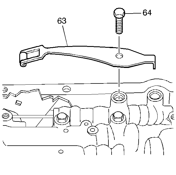
- Remove the manual detent spring bolt (64).
- Remove the manual detent spring assembly (63).
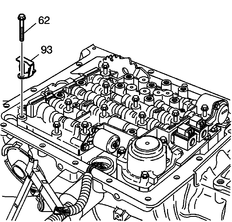
- Remove all valve body bolts (62).
- Remove the fluid level indicator stop bracket (93).
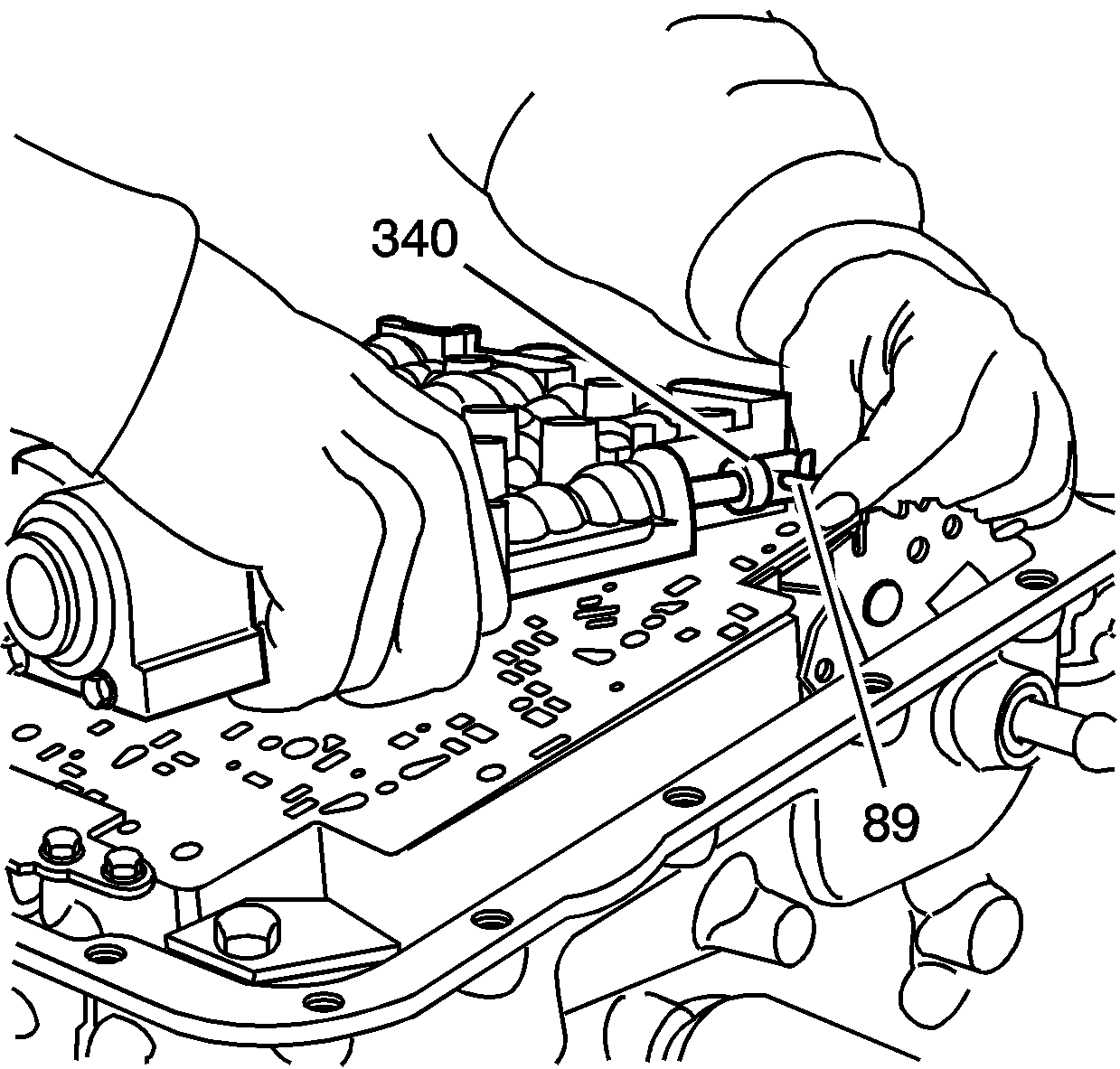
- Lift the valve body carefully so that the checkballs remain on the spacer plate in the correct location. While lifting the valve body, disconnect the manual valve link from the manual valve.
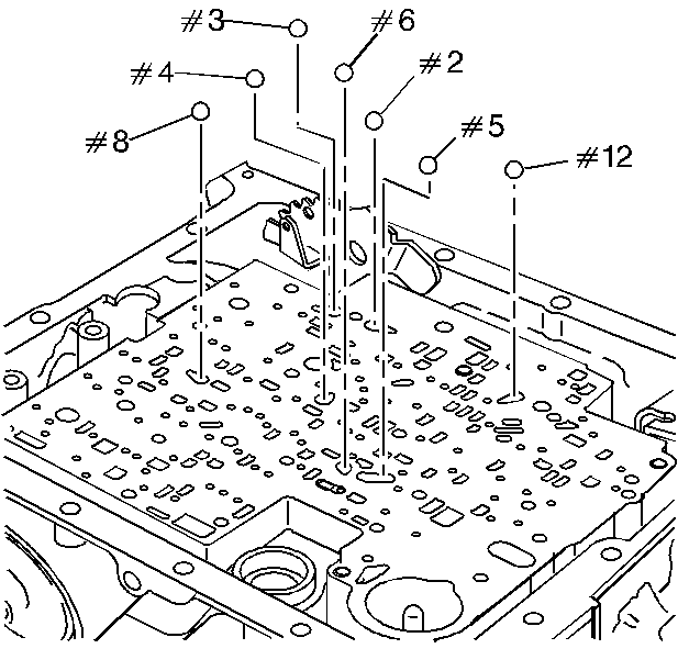
- Remove the seven valve body checkballs (2-6, 8, 12).
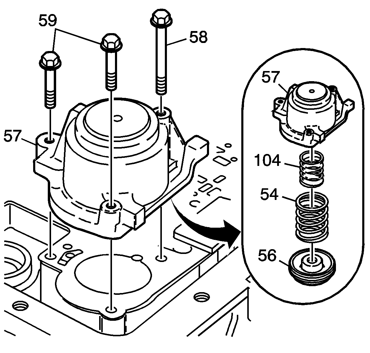
- Remove the accumulator cover bolts (58, 59).
- Remove the 1-2 accumulator cover and pin assembly (57).
- Disassemble the 1-2 accumulator assembly (54, 56, 57, 104).
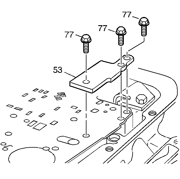
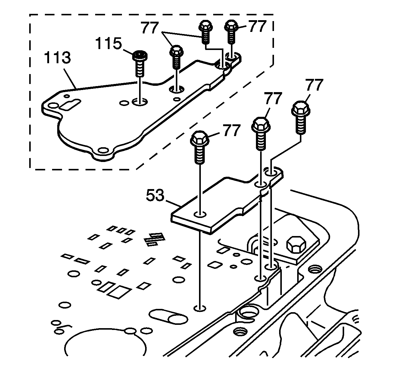
- Remove the spacer plate support bolts (77).
- Remove the spacer plate support (53).
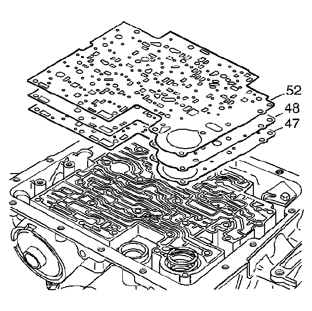
- Remove the valve body gasket (52), the valve body spacer plate (48) and the case gasket (47).
- Remove the 3-4 accumulator spring (model dependent) and the 3-4 accumulator piston.
- Remove the case checkball (#1).
Notice: Do not use a magnet in order to remove the control valve body ball check valves. This may magnetize the control valve body ball check valves, causing metal particles to stick to them.
Discard gaskets. Do not reuse.
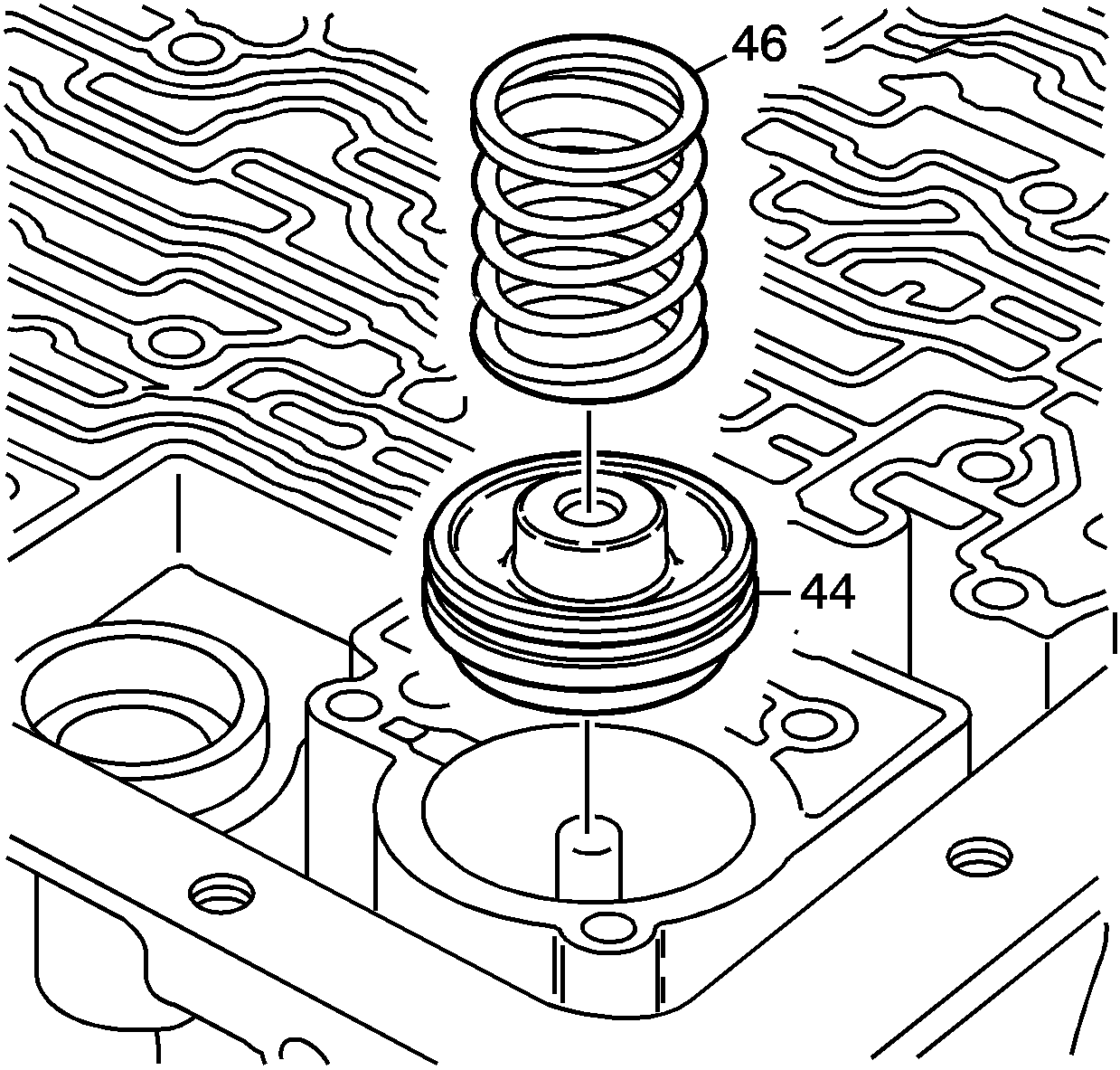
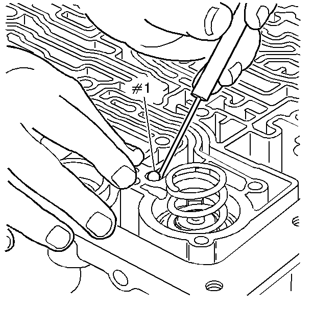
Notice: Do not use a magnet in order to remove the control valve body ball check valves. This may magnetize the control valve body ball check valves, causing metal particles to stick to them.
- Remove all electrical connectors (1-6) from the electrical components.
- Remove the torque converter clutch (TCC/PWM) pulse width modulation retainer clip (395).
- Remove the TCC/PWM solenoid (396).
- Remove the TCC solenoid bolts (68).
- Remove the TCC solenoid and wiring harness (66). Turn the wiring harness over so that it hangs over the side of the transmission.
- Remove the transmission fluid pressure (TFP) manual valve position switch assembly bolts (62, 70).
- Remove the TFP manual valve position switch (69).
- Remove the manual detent spring bolt (64).
- Remove the manual detent spring assembly (63).
- Remove all valve body bolts (62).
- Remove the fluid level indicator stop bracket (93) - model dependent.
- Lift the valve body carefully so that the checkballs remain on the spacer plate in the correct location. While lifting the valve body, disconnect the manual valve link from the manual valve.
- Remove the 7 valve body checkballs (2-6, 8, 12).
- Remove the accumulator cover bolts (58, 59 or 117, 118).
- Remove the 1-2 accumulator cover and pin assembly (57 or 116).
- Disassemble the 1-2 accumulator assembly (54, 56, 57, 104).
- Remove the spacer plate support bolts (77).
- Remove the spacer plate support (53 or 113).
- Remove the valve body gasket (52), the valve body spacer plate (48) and the case gasket (47).
- Remove the 3-4 accumulator spring (model dependent) and the 3-4 accumulator piston.
- Remove the case checkball (#1).


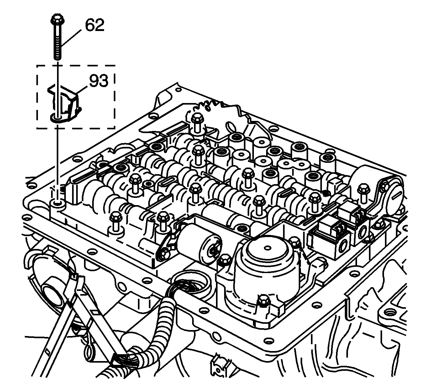
Important: Fluid level indicator stop bracket is model dependent. Some models do not have a dipstick stop.


Notice: Do not use a magnet in order to remove the control valve body ball check valves. This may magnetize the control valve body ball check valves, causing metal particles to stick to them.
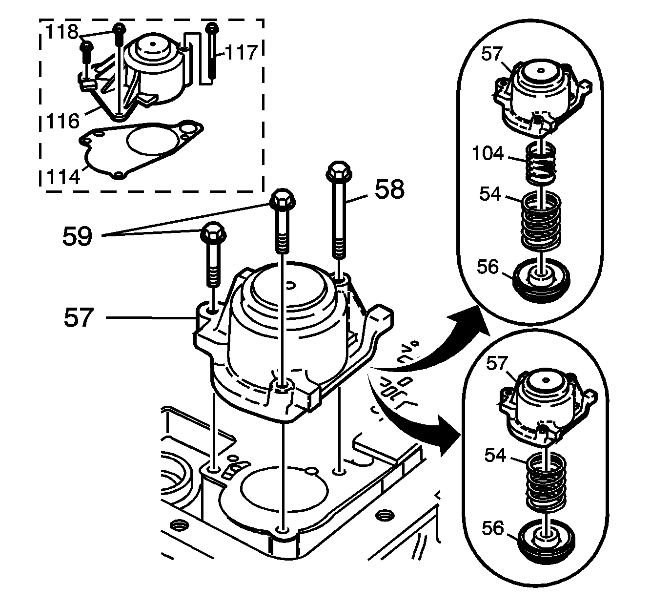
Important: M33 models do not use 1-2 accumulator spring - inner (104).
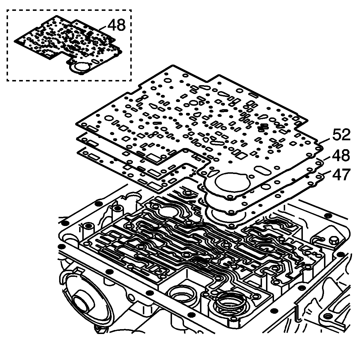
Important: Some models use a bonded spacer plate (48). Do not reuse the bonded spacer plate. Replace with a NEW bonded spacer plate.
Discard gaskets. Do not reuse.


Notice: Do not use a magnet in order to remove the control valve body ball check valves. This may magnetize the control valve body ball check valves, causing metal particles to stick to them.
