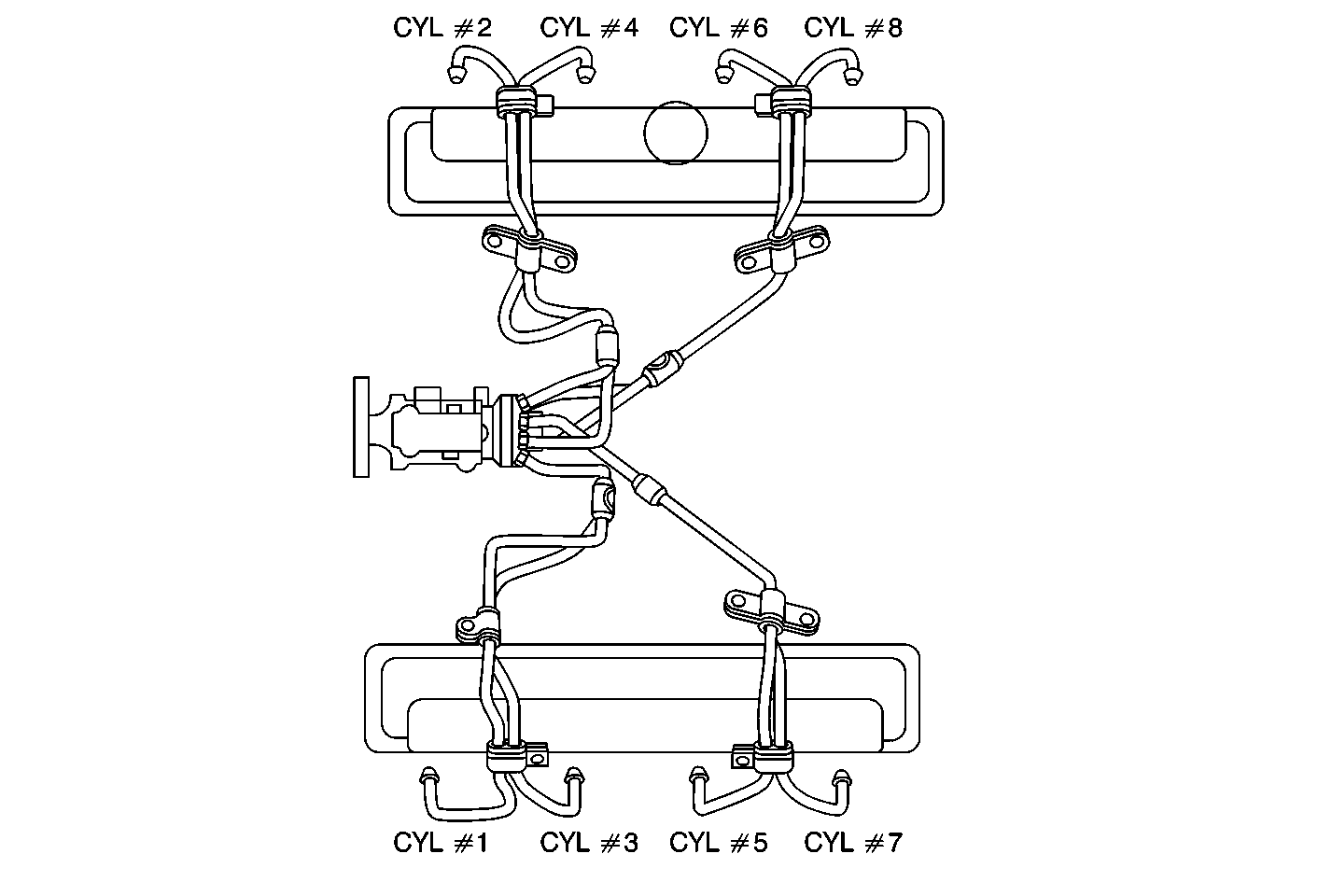
Circuit Description
The powertrain control module (PCM) times the intervals between each pulse of the crankshaft position sensor and compares each time interval with the other 7 to determine when an excessive change in crankshaft speed has occurred. This pulse is generated from a 4X reluctor wheel located on the front of the crankshaft. If the crankshaft speed is less than an expected amount, the PCM will increase the amount of fuel needed to correct the misfire. If the amount of fuel exceeds the calibrated value, the PCM will interpret this as a misfire and set the DTC. The misfire diagnostic is used only to identify a weak cylinder needing additional fuel. This diagnostic will only run once per ignition cycle.
Conditions for Running the DTC
| • | The engine coolant temperature more than 56°C (132°F) |
| • | The engine is idling for a total of 90 seconds |
Conditions for Setting the DTC
The amount of fuel added is more than the calibrated value (internal to PCM).
Action Taken When the DTC Sets
| • | The PCM illuminates the malfunction indicator lamp (MIL) on the second consecutive drive trip the diagnostic runs and fails. |
| • | The PCM records the operating conditions at the time the diagnostic fails. The first time the diagnostic fails, the Failure Records store this information. If the diagnostic reports a failure on the second consecutive drive trip, the Freeze Frame records the operating conditions at the time of failure and updates the Failure Records. |
Conditions for Clearing the MIL/DTC
| • | A history DTC clears after 40 consecutive warm-up cycles, if this or any other emission related diagnostic does not report any failures. |
| • | The scan tool Clear Info function was used. |
Diagnostic Aids
The most likely cause for this DTC is the following:
| • | A mechanical failure causing low cylinder compression |
| • | A fuel leak at the high pressure fuel injection lines or injection nozzles |
| • | A fuel injection nozzle stuck closed |
If an injection nozzle is suspected, it can be transferred to another cylinder to determine if the DTC follows the nozzle.
After the repair has been performed, it may take approximately 30 seconds for the vehicle to return to a stable idle.
Test Description
The numbers below refer to the step numbers on the diagnostic table:
Step | Action | Values | Yes | No | ||||||
|---|---|---|---|---|---|---|---|---|---|---|
1 |
Important: Before clearing the DTCs, use the scan tool Capture Info to save the Freeze Frame and Failure Records for reference. The data in the control module is deleted once the Clear Info function is used. Did you perform the Powertrain On-Board Diagnostic (OBD) System Check? | -- | ||||||||
Is there an RPM drop in the suspected cylinder? | -- | |||||||||
3 | The DTC is intermittent. If no additional DTCs are stored, refer to diagnostic aids. If any additional DTCs were stored, refer to the applicable DTC tables first. Are there any DTCs stored? | -- | Go to the applicable DTC table | Go to Diagnostic Aids | ||||||
Did you perform a repair? | -- | |||||||||
5 | Replace the fuel injection pump. Refer to Fuel Injection Pump Replacement . Is action complete? | -- | -- | |||||||
6 |
Does the scan tool indicate the diagnostic Passed? | -- | ||||||||
7 | Does the scan tool display any additional undiagnosed DTCs? | -- | Go to the applicable DTC table | System OK |
