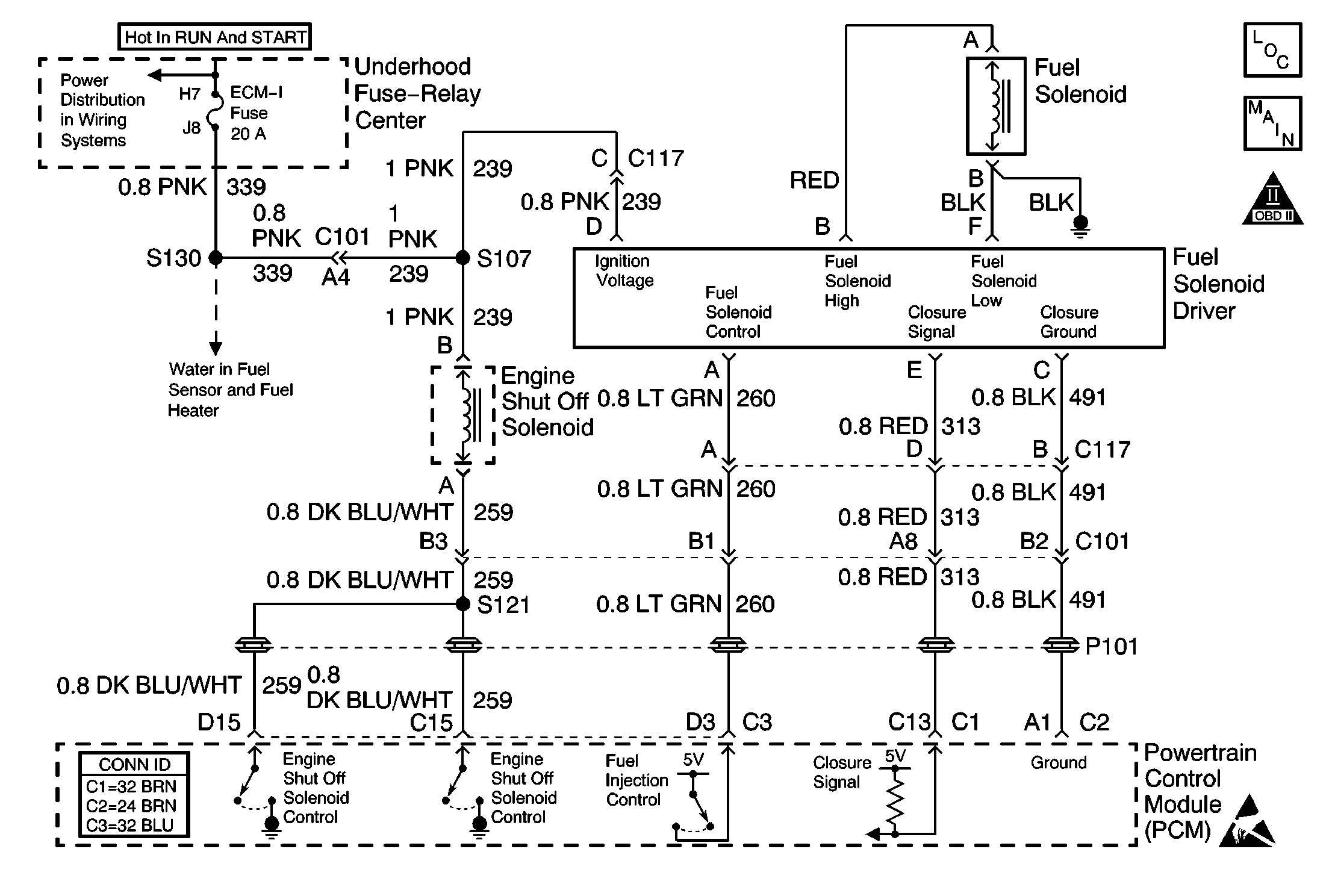
Circuit Description
The Fuel Solenoid Driver is a high current switch which receives inject commands from the PCM. The Fuel Solenoid Driver energizes and de-energizes the fuel control solenoid at precise intervals in order to achieve accurate control of the fuel delivery at all throttle positions and speeds. The Fuel Solenoid Driver supplies ignition voltage to the fuel control solenoid. The Fuel Solenoid Driver also contains circuitry that enables it to sense poppet valve closure, or closure time. This information is transmitted back to the PCM. If the ignition voltage is low, either through faulty connections, charging system failure, low batteries, or after market add-ons, it is possible that a slow closure time will occur. The Fuel Solenoid Driver is located on the right side of the injection pump as viewed from the front of the vehicle. The Fuel Solenoid Driver utilizes a closure ground circuit, an ignition voltage circuit, a fuel inject control circuit and a closure signal circuit.
Diagnostic Aids
Important: Because it is difficult to diagnosis intermittent conditions, it is critical that every step of the diagnostic table be performed with thoroughness. Since many other failures can cause similar symptoms to that of a failed Fuel Solenoid Driver, the elimination of other, simpler causes of the failure should be eliminated before a Fuel Solenoid Driver is replaced.
It is also important to perform visual checks for a pinched harness at the intake manifold and the turbocharger, and for proper wiring connections at the engine connector. The Fuel Solenoid Driver can be visually checked for an obvious failure. A shorted fuel solenoid driver may cause the ECM 1 fuse to fail. This type of failure can be associated with a No Start concern. Possible Symptoms of a Fuel Solenoid Driver are:
| • | No starts |
| • | Stalling |
| • | Intermittent stumble or "fish bite" |
| • | Surging |
An intermittent can be caused by the following:
| • | Faulty connections |
| • | Rubbed-through wire insulation |
| • | Broken wire inside the insulation |
Test Description
The numbers below refer to the step numbers on the Diagnostic Table.
-
This step will check the ground wire on the injection pump. The wire is located on the top of the pump.
-
This step will determine if proper voltage is going to the fuel solenoid driver.
Step | Action | Value(s) | Yes | No |
|---|---|---|---|---|
1 |
Important: Before clearing the DTCs use the Scan Tool Capture Info in order to record the Freeze Frame and Failure Records for reference. Data will be lost when the Clear Info function is used. Did you perform the Powertrain On-Board Diagnostic (OBD) System Check? | -- | ||
2 | Check for proper condition of batteries. Refer to Battery Inspection/Test . Is the condition of batteries OK? | -- | ||
3 | Check for adequate fuel in the tank. Is the fuel at an adequate level? | -- | ||
4 | Check the quality of the fuel. Is the fuel quality OK? | -- | ||
5 | Check the Injection Pump Timing. Refer to Fuel Injection Pump Timing Adjustment . Is injection timing OK? | -- | ||
6 | Check for the proper cranking speed. Is the cranking speed OK? | 100 RPM cold 180 RPM hot | ||
7 | Check for a restriction in the fuel return system. Refer to Fuel Return System Diagnosis . Does the fuel return system operate properly? | -- | ||
Check the injection pump ground wire, located on the top of the injection pump. Is the ground OK? | -- | |||
9 | Check for air in the fuel system. Refer to Fuel Feed Pipe and Return Pipe Purging . Is there any air in the fuel system? | -- | ||
10 | Check for a faulty connection or corrosion in the fuel solenoid closure ground circuit. Did you perform a repair? | -- | ||
11 | Check for a faulty connection or corrosion in the fuel inject circuit. Did you perform a repair? | -- | ||
Is voltage at the specified value during the condition which is causing the complaint? | B+ | |||
13 | Check for a proper connection or corrosion in the fuel connector at the injection pump. Did you perform a repair? | -- | ||
14 | Check for a faulty connection or corrosion in the engine and vehicle ground circuits, located at the rear of the intake manifold. Did you perform a repair? | -- | ||
15 |
| -- | ||
16 | Replace fuel solenoid driver. Refer to Fuel Solenoid Driver Replacement . Is the action complete? | -- | -- | |
17 | Make the appropriate repairs. Is the action complete? | -- | -- | |
18 | Verify that the condition has been repaired. Is the action complete? | -- | Injection System OK | Go to Symptoms |
