Removal Procedure
Tools Required
J 41602 Body Protection Hoist Adapter Set
- Raise the vehicle. Refer to Lifting and Jacking the Vehicle in General Information.
- Support the axle separately.
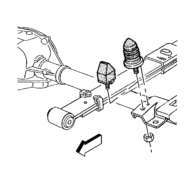
- If necessary to gain access to the lower plate front nut, remove the axle bumper and the nut.
- With a stabilizer shaft, it will be necessary to remove the following parts:
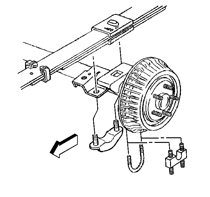
- Remove the U-bolt and the lower plate to the anchor plate nuts.
- Remove the U-bolt.
- Remove the lower plate.
- Remove the anchor plate.
- Lower the axle away from the spring.
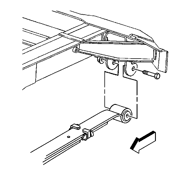
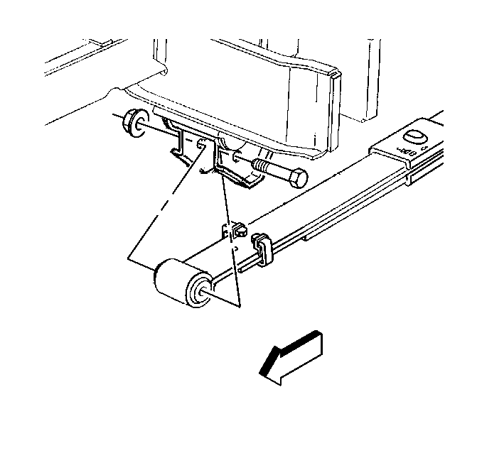
- Remove the shackle nut and the bolt.
- Remove the spring from the shackle.
- Remove the hanger nut and the bolt.
- Remove the spring from the hanger.
Use the J 41602 in order to lift at the pinch welds if necessary.
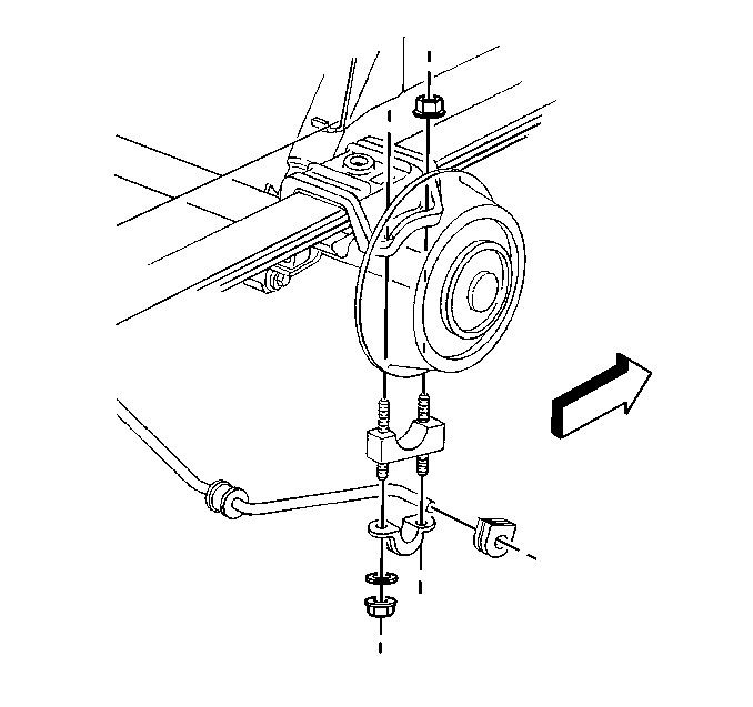
| • | The lower nuts |
| • | The washers |
| • | The clamps |
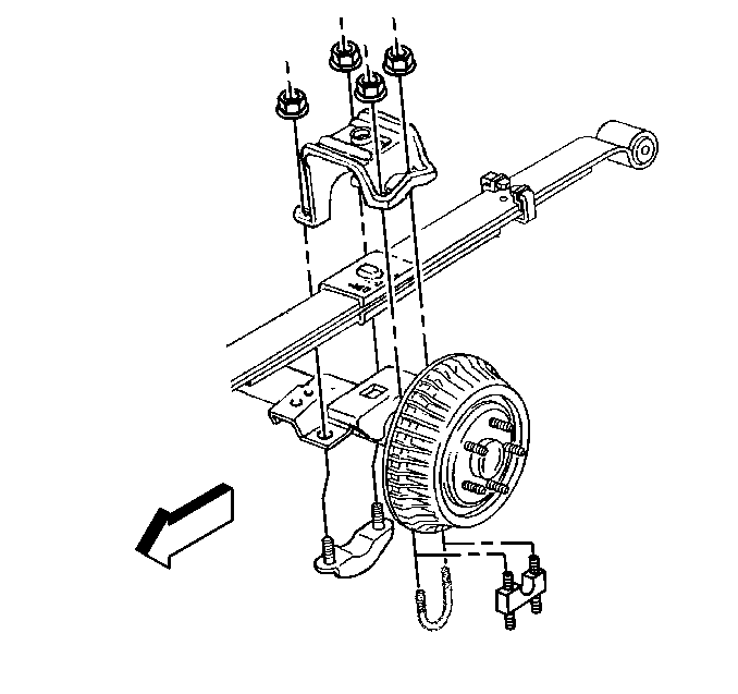
Notice: Do not let the axle hang by the brake hose. Damage to the hose may occur. Always support the axle and the body separately.
Installation Procedure
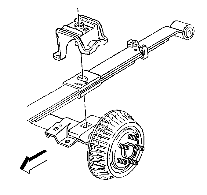
Important: In order to achieve the proper seating and the proper attachment of the anchor plate over both the spring and the axle, the following procedure must be used.
- Install the spring to the hanger.
- Loosely install the hanger bolt and the nut.
- Install the spring to the shackle.
- Loosely install the shackle bolt and the nut.
- Install the axle to the spring.
- Install the anchor plate to the top of the spring.
- Install the lower plate and the U-bolt around the axle and through the anchor plate.
- Install the 4 nuts to the lower plate and the U-bolt.
- Starting with the inner (lower plate side) nuts, gradually tighten the four nuts so that the anchor plate moves uniformly, side to side, over the spring.
- For a stabilizer shaft, install the following parts:
- Install the axle bumper.
- Install the axle bumper nut.
- Lower the vehicle.
- Remove the J 41602 if necessary.
- Adjust the trim height of the vehicle. Refer to Trim Height Inspection in Suspension General Diagnosis.


Raise the axle so that the axle butts against the spring.

Apply the rubber lubricant (GM P/N 12345884 or equivalent) to the isolator on the spring in order to aid in installation of the anchor plate to the spring.
Important: After tightening the fasteners to the specified torque, ensure that there is no gap between the anchor plate, the axle tube bracket, and the lower plate. The contact should be metal to metal.
Notice: Use the correct fastener in the correct location. Replacement fasteners must be the correct part number for that application. Fasteners requiring replacement or fasteners requiring the use of thread locking compound or sealant are identified in the service procedure. Do not use paints, lubricants, or corrosion inhibitors on fasteners or fastener joint surfaces unless specified. These coatings affect fastener torque and joint clamping force and may damage the fastener. Use the correct tightening sequence and specifications when installing fasteners in order to avoid damage to parts and systems.
Tighten
Tighten the anchor plate nuts to 61 N·m (45 lb ft).

| • | The clamps |
| • | The washers |
| • | The nuts |

Tighten
| • | Tighten the axle bumper nut to 45 N·m (33 lb ft). |
| • | Tighten the hanger nut and the hanger bolt to 100 N·m (74 lb ft). |
| • | Tighten the shackle nut and the shackle bolt to 100 N·m (74 lb ft). |
