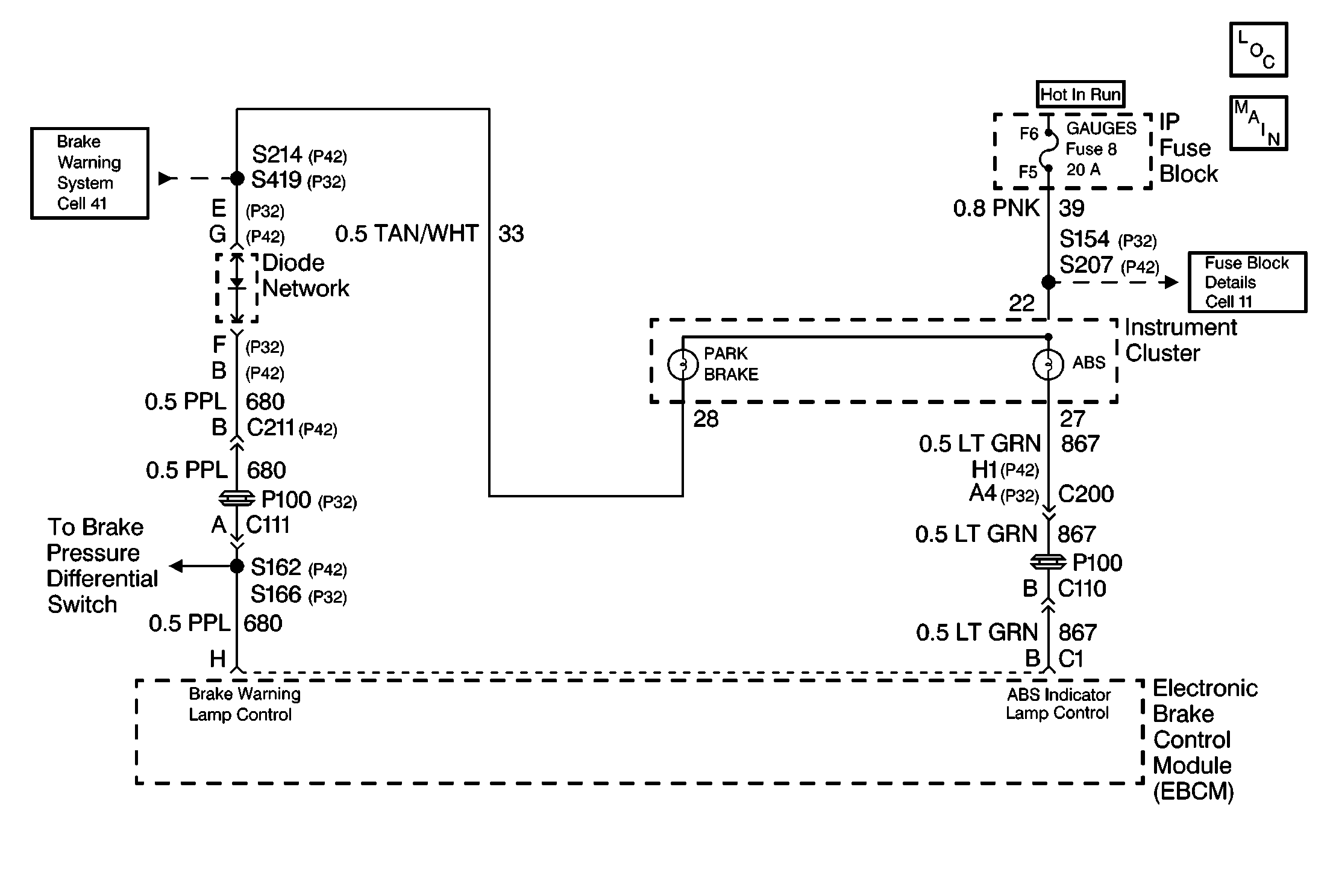
Circuit Description
The amber ANTILOCK indicator lamp is supplied ignition voltage through the GAUGES fuse. The ABS indicator lamp is normally on (EBCM terminal B grounded) until the EBCM switches the indicator off (normal mode). This logic ensures that the indicator will be illuminated if there is a faulty EBCM.
Conditions for Setting the DTC
| • | High voltage is present on the ABS indicator lamp control circuit when low voltage is expected (lamp is turned on) to be low |
| • | Anything that keeps the ABS indicator lamp circuit high when the lamp circuit is expected to be on |
Action Taken When the DTC Sets
| • | The ABS is not disabled |
| • | The EBCM will use the red BRAKE warning lamp to alert the driver of an ABS malfunction |
Conditions for Clearing the DTC
| • | Repair the conditions responsible for setting the DTC |
| • | Use the Scan Tool Clear DTCs function |
Diagnostic Aids
DTC C0286 typically sets because of a shorted amber ABS indicator lamp. Yet DTC C0286 can also set because of a short to voltage in the wiring between the amber ABS indicator lamp and the EBCM.
Test Description
The numbers below refer to the steps in the diagnostic table:
-
This step checks for normal operation of the ABS indicator lamp.
-
This step turns off the ABS indicator lamp with a J 36169-A .
Step | Action | Value(s) | Yes | No |
|---|---|---|---|---|
1 | Was the Diagnostic System Check performed? | -- | Go to Diagnostic System Check | |
| -- | |||
Does the ABS indicator lamp turn on? | -- | |||
4 | Inspect the jumper wire fuse. Is the fuse open? | -- | ||
5 | Malfunction is intermittent, perform the following:
Is the repair complete? | -- | Go to Diagnostic System Check | Malfunction is intermittent. Go to Diagnostic Aids |
6 | Replace the EBCM. Is repair complete? | -- | Go to Diagnostic System Check | -- |
7 | Repair a short to voltage in CKT 867. Is the repair complete? | -- | Go to Diagnostic System Check | -- |
