CLUTCH DRAG OR NO/POOR RELEASE DIAGNOSIS/SERVICE PROCEDURES

SUBJECT: CLUTCH WILL NOT RELEASE/HARD SHIFT/CLUTCH DRAG/GEAR CLASH/VEHICLE CREEP
MODELS: 1990 C7H TOPKICK/KODIAKS EQUIPPED WITH CATERPILLAR 3116 ENGINES (RPO LXO) WITH 215 OR 250 POWER OPTIONS (RPO's LVY or LVZ), FULLER 5 OR 6 SPEED TRANSMISSIONS FS6105, FS5106, FS6206 OR FS7206 AND 13" LIPE DUAL PLATE "PULL" TYPE CLUTCHES
Some of the above subject vehicles may experience clutch drag, hard shifting, gear clash, vehicle creep or no/poor clutch release. These conditions can occur in vehicles equipped with Lipe dual 13" "pull" type clutch assemblies if the positive separation control roll pins are an incorrect length or improperly positioned.
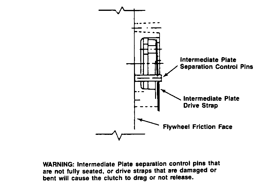
There are four positive intermediate plate separation control roll pins. These pins control the centering of the intermediate plate between the two dampened discs. The pins are located on the intermediate plate and align (contact) the flywheel friction face.
Determine if the pin length is correct. The length of the pins should be 1.265" - 1.269". Pins that are incorrect lengths will cause the clutch to drag or not release. If the pins are too long, the front disc will bind. If the pins are too short, the rear disc will bind.
Care should be taken during pin removal. If the pins are damaged, it is necessary to install new pins.
Pins are not available from GMSPO.-Contact Midland Heavy Duty Systems Customer Service Department (1-800-643-2374) for the nearest Lipe distributor in your area. The Midland pin part number is C087-0009.
To determine if improper installation of the separation control roll pins exists, it is necessary to first check the following clutch adjustments.
1. Since synchronized transmissions do not require the use of brake discs, the gap between the release bearing housing and the transmission front bearing cap should be approximately 5/8" to 3/4".
To obtain the proper clearance, unlock the release bearing sleeve locknut and rotate the release bearing sleeve clockwise or counter-clockwise as required until the proper dimension has been obtained. Relock the sleeve locknut securely.
2. Check for proper clutch cable free travel. Proper clutch cable free travel should be approximately 1-1/2" to 2". Measure by pressing the clutch pedal downward with your hand until slight clutch resistance is felt. No disengagement of the clutch should occur.
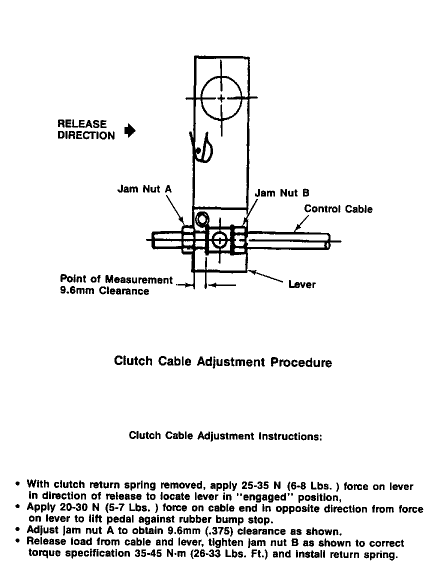
To obtain the 1-1/2" to 2" of pedal free travel, adjust the clutch cable until there is approximately 1/8' between the release yoke and the release bearing (Figure 1).
3. Check for proper release bearing travel. Total release bearing travel should be approximately 7/16' to 9/16'.
4. Remove the engine inspection cover and inspect the four intermediate plate positive separation control roll pins to determine if they are fully seated (Figure 2). There should be zero clearance between each of the four positive separation control roll pins and the fly- wheel friction face.
To check each of the four roll pins to determine if they are fully seated, it is necessary to rotate the engine manually 90 degrees per roll pin with the clutch engaged (pedal not depressed).
If zero clearance is found on all four roll pins, no further checks are needed at this time regarding the pins.
If it is determined any of the four roll pins are not fully seated, it is necessary to reposition all four roll pins fully against the flywheel friction face. While the clutch pedal is fully depressed, pry the intermediate plate rearward away from the flywheel. This action positions the roll pins forward when the clutch is engaged.
NOTE: All four ro# pins MUST be properly positioned prior to clutch engagement.
WARRANTY INFORMATION:
For vehicles repaired under warranty use:
Labor Operation Description --------- ------------------------- K0020 Clutch Linkage Adjust K0800 Disc and/or Clutch Cover-Clutch Replace
(Refer to Figure 1)
o With clutch return spring removed, apply 25-35 N (6-8 Lbs. ) force an lever in direction of release to locate lever in "engaged" position,
o Apply 20-30 N (5-7 Lbs. ) force on cable end in opposite direction from force on lever to lift pedal against rubber bump stop.
o Adjust jam nut A to obtain 9.6mm (.375) clearance as shown.
o Release load from cable and lever, tighten jam nut B as shown to correct torque specification 35-45 N-m (26-33 Lbs. Ft.) and install return spring.
WARNING: Intermediate Plate separation control pins that are not fully seated, or drive straps that are damaged or bent will cause the clutch to drag or not release.


General Motors bulletins are intended for use by professional technicians, not a "do-it-yourselfer". They are written to inform those technicians of conditions that may occur on some vehicles, or to provide information that could assist in the proper service of a vehicle. Properly trained technicians have the equipment, tools, safety instructions and know-how to do a job properly and safely. If a condition is described, do not assume that the bulletin applies to your vehicle, or that your vehicle will have that condition. See a General Motors dealer servicing your brand of General Motors vehicle for information on whether your vehicle may benefit from the information.
