- Set the parking brake.
- Block the vehicle rear wheels.
- Lift the vehicle frame until the front tire is off the ground.
- Support the frame using suitable safety stands.
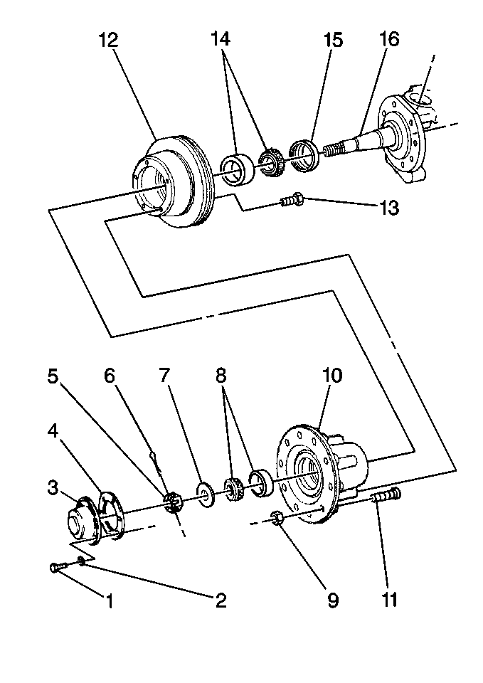
- Remove the bolts (1) and the washers (2). (The illustration shows a wheel hub with disc brakes, but you will perform the bearing adjustment in the same manner for any kind of axle.)
- Remove the hub cap (3) and the gasket (4). DO NOT allow the gasket material to fall into the hub, where applicable.
- Remove the cotter pin (6).
- Adjust the nut (5).
- Back off the nut 1/4-1/6 turn until the slot in the nut lines up with hole in the spindle (16) of the steering knuckle.
- Install a new cotter pin (6). Bend the cotter pin for proper clearance of the rotating components.
- Install a new gasket (4) and align the gasket properly. Attach the hub cap (3).
- Install the hub cap bolts (1) with new washers (2).
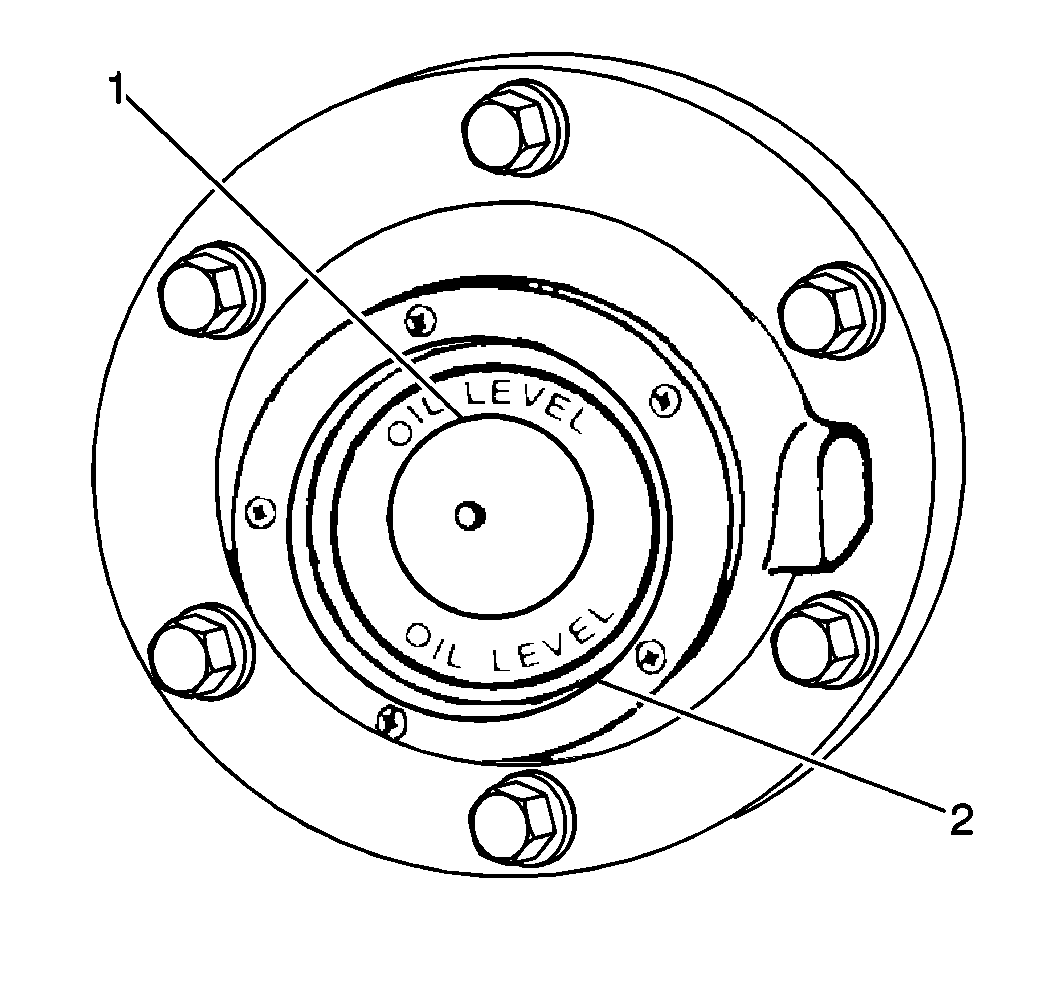
- Add new lubricant to the oil lubricated bearings (1) only. Refer to Adding Lubricant to Hub Caps .
- Remove the safety stands.
- Lower the vehicle.
Notice: Perform the following steps before beginning any vehicle lifting or
jacking procedure:
• Remove or secure all of the vehicle's contents in order to avoid
any shifting or any movement that may occur during the vehicle lifting or
jacking procedure. • The lifting equipment or the jacking equipment weight rating must
meet or exceed the weight of the vehicle and any vehicle contents. • The lifting equipment or the jacking equipment must meet the operational
standards of the lifting equipment or jacking equipment's manufacturer. • Perform the vehicle lifting or jacking procedure on a clean, hard,
dry, level surface. • Perform the vehicle lifting or jacking procedure only at the identified
lift points. DO NOT allow the lifting equipment or jacking equipment to contact
any other vehicle components.

Notice: Use the correct fastener in the correct location. Replacement fasteners must be the correct part number for that application. Fasteners requiring replacement or fasteners requiring the use of thread locking compound or sealant are identified in the service procedure. Do not use paints, lubricants, or corrosion inhibitors on fasteners or fastener joint surfaces unless specified. These coatings affect fastener torque and joint clamping force and may damage the fastener. Use the correct tightening sequence and specifications when installing fasteners in order to avoid damage to parts and systems.
Tighten
Tighten the nut to 153 N·m (113 lb ft) while
rotating the wheel 360 degrees in both directions. This rotation will
correctly position the bearings.
Important: Always back off the nut 1/4-1/6 turn. This adjustment should result in bearing end play of 0.025-0.200 mm (0.001-0.008 in).
Notice: Use the correct fastener in the correct location. Replacement fasteners must be the correct part number for that application. Fasteners requiring replacement or fasteners requiring the use of thread locking compound or sealant are identified in the service procedure. Do not use paints, lubricants, or corrosion inhibitors on fasteners or fastener joint surfaces unless specified. These coatings affect fastener torque and joint clamping force and may damage the fastener. Use the correct tightening sequence and specifications when installing fasteners in order to avoid damage to parts and systems.
Tighten
Tighten the hub cap bolts evenly to 13 N·m (115 lb in).

