Special Tools
| • | EN-45059 Torque Angle Sensor Kit
|
| • | EN-48249 Piston Ring Compressor
|
For equivalent regional tools, refer to
Special Tools.
Removal Procedure
- Remove the cylinder head. Refer to
Cylinder Head Replacement.
- Remove the oil pan. Refer to
Oil Pan Replacement.
- Raise the vehicle by its full height. Refer to
Lifting and Jacking the Vehicle.
- Install the crankshaft balancer bolt.
- Set the pistons 1 and 4 to BDC in direction of engine rotation.
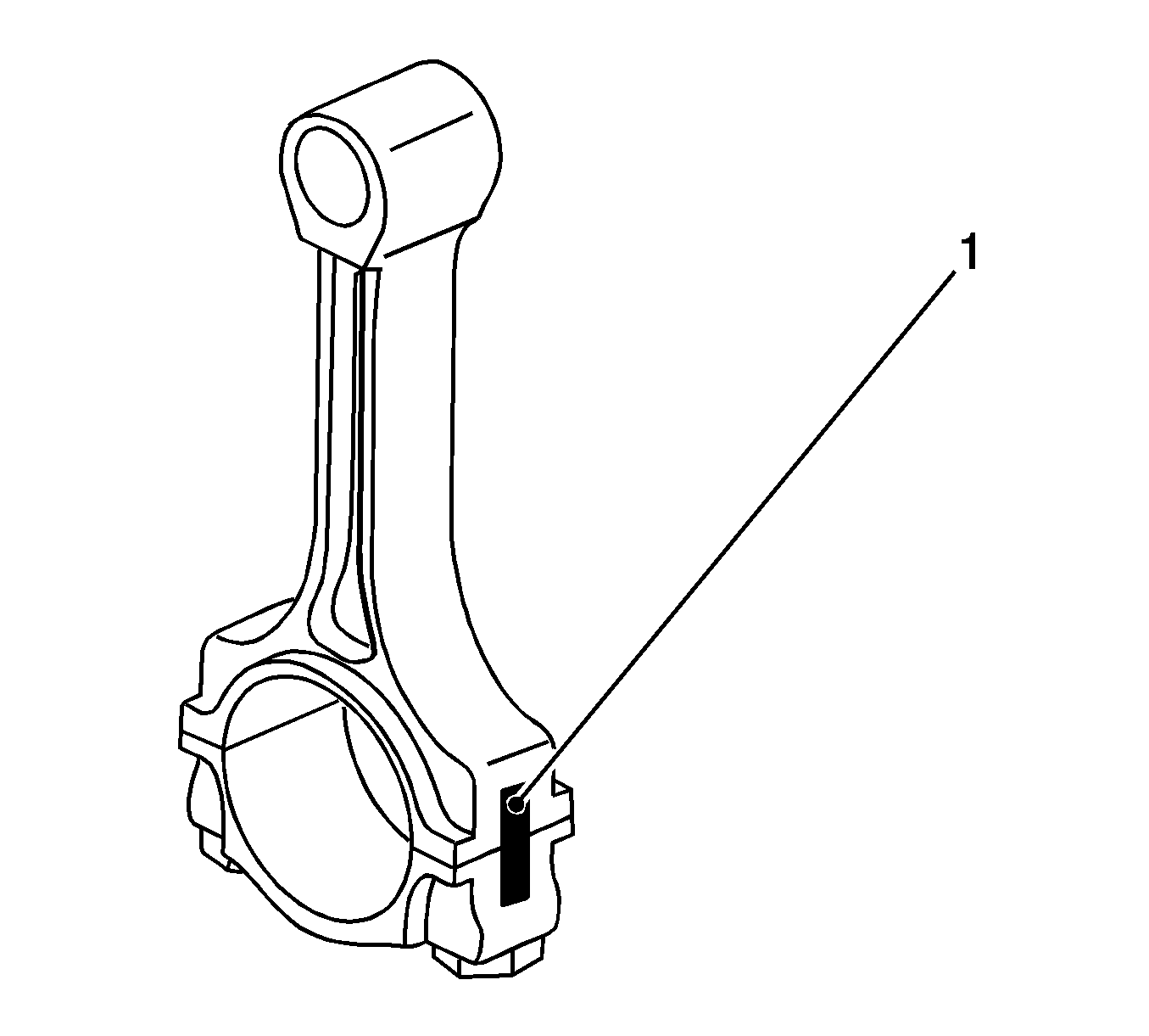
Note: Note cylinder sequence.
- Mark the connecting rod with the connecting rod bearing cover (1).
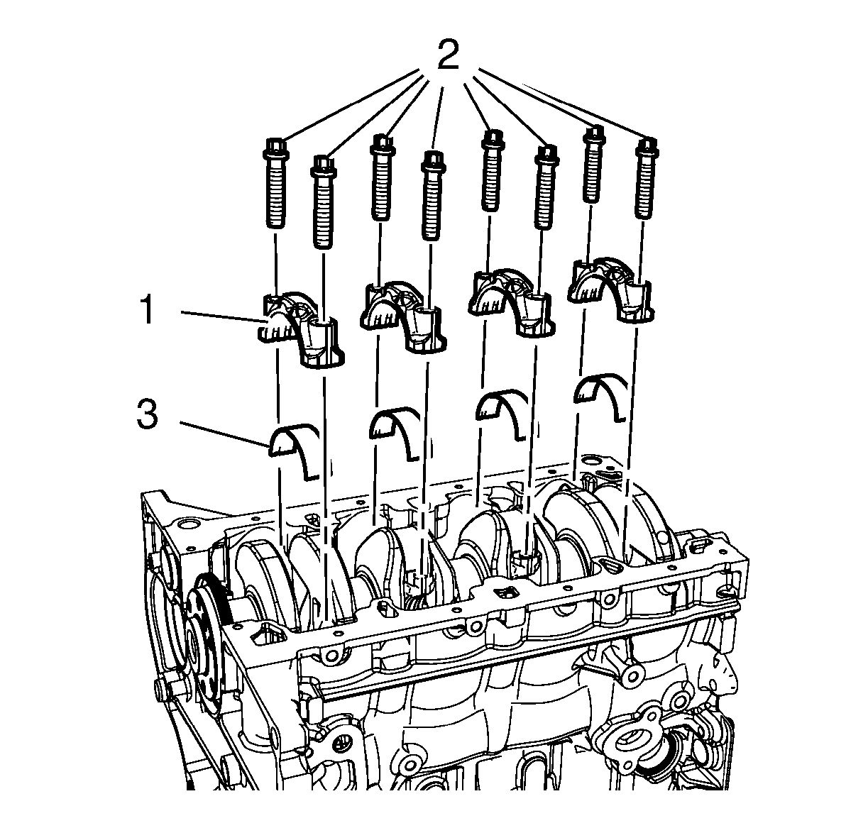
- Remove the 4 connecting rod bearing caps bolts (2) of cylinder 1 and 4.
- Remove the connecting rod bearing caps (1) and the connecting rod bearing (3).
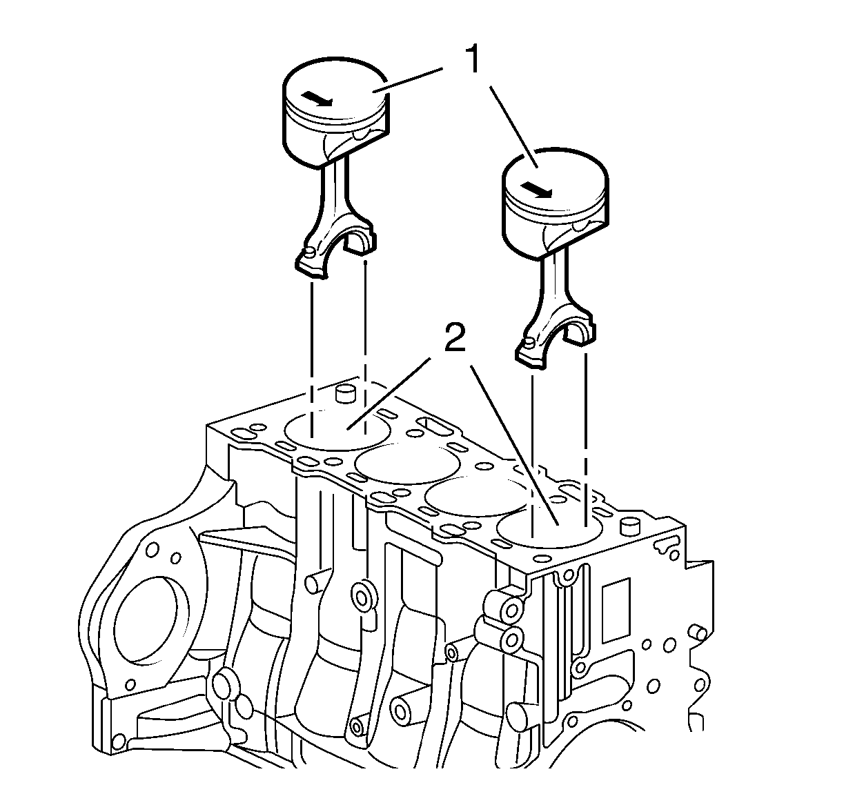
- Push the pistons 1 and 4 (1) out of the cylinder bore (2).
- Lower the vehicle by its full height.
Note: The shear surfaces of the con-rod and the con-rod bearing cover form a unique fit and must not be swapped or damaged. Do not lay down on the shear surfaces.
- Remove the pistons 1 and 4 (1).
- Raise the vehicle by its full height.
- Turn crankshaft on crankshaft balancer through 180 degrees in direction of rotation of engine.

Note: Note cylinder sequence.
- Mark the connecting rod with the connecting rod bearing cover (1).

- Remove the 4 connecting rod bearing caps bolts (2) of cylinder 2 and 3.
- Remove the connecting rod bearing caps (1) and the connecting rod bearing (3).
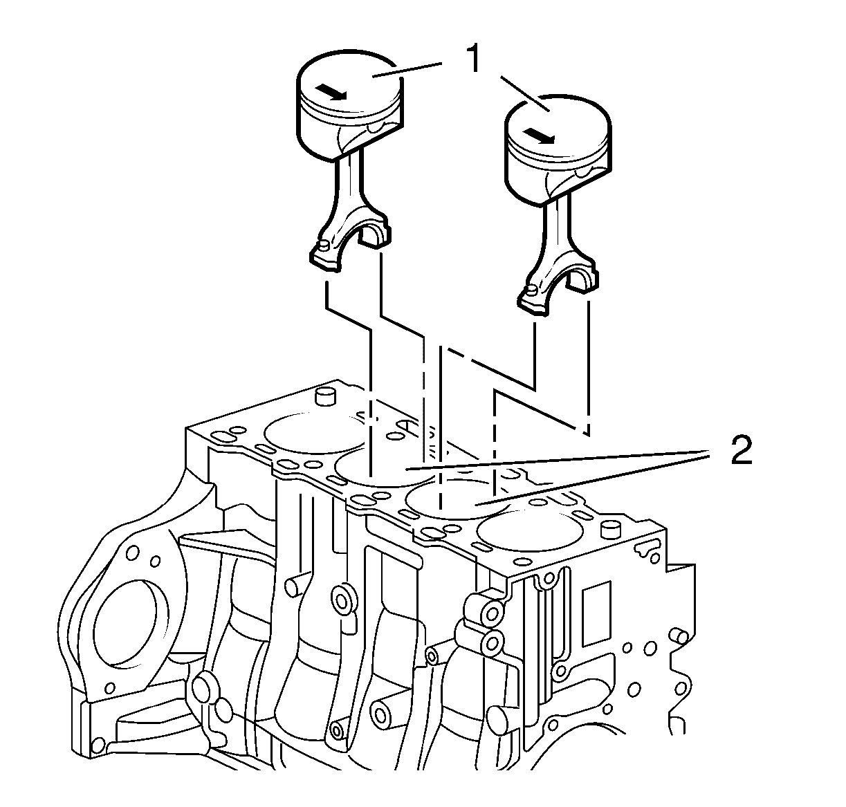
- Push the pistons 2 and 3 (1) out of the cylinder bore (2).
- Lower the vehicle by its full height.
Note: The shear surfaces of the con-rod and the con-rod bearing cover form a unique fit and must not be swapped or damaged. Do not lay down on the shear surfaces.
- Remove the pistons 2 and 3 (1).
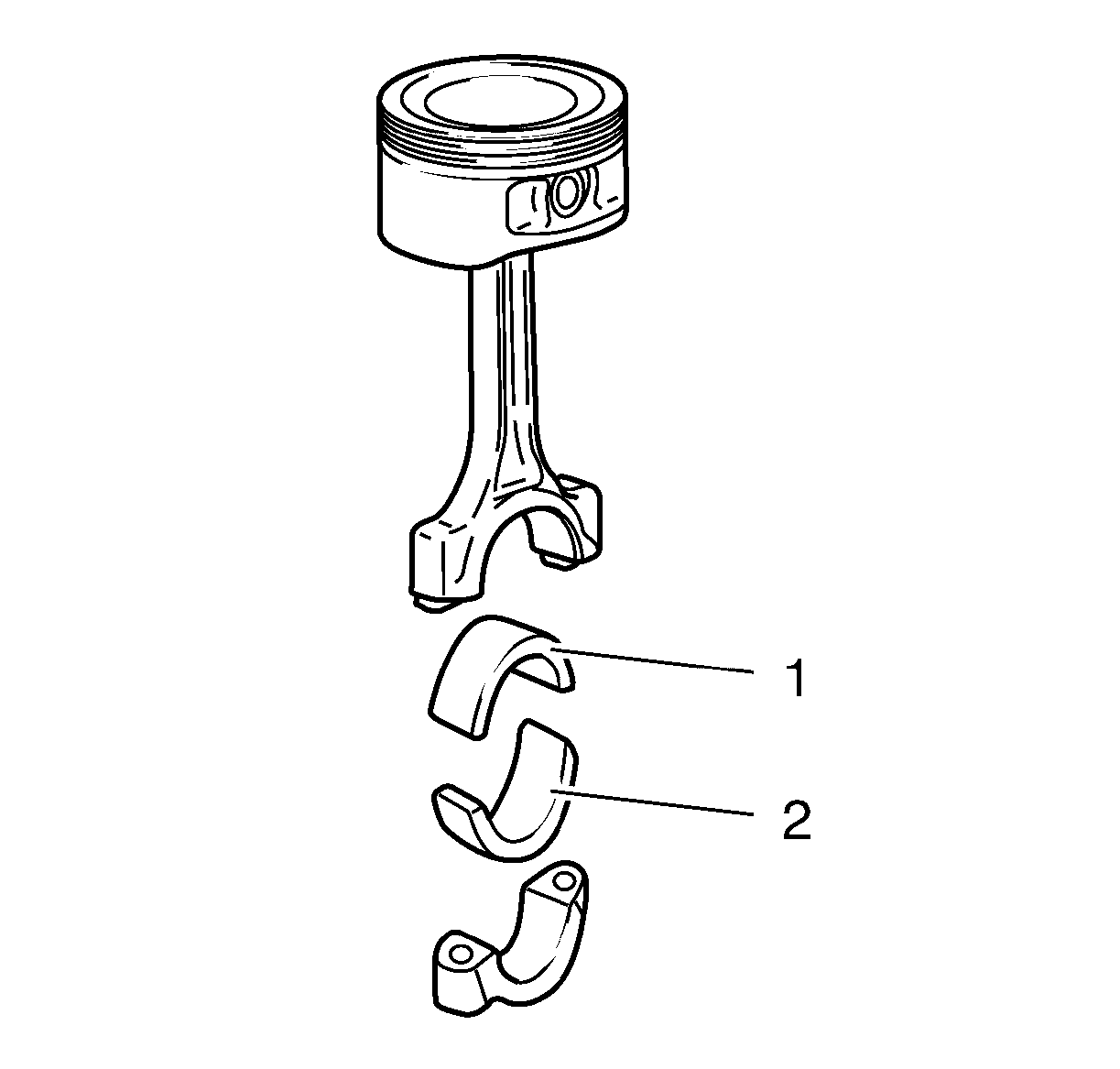
Note: Observe correct fitting position, observe alignment.
- Remove the connecting rod bearing (1, 2).
- Check the components. Refer to
Piston, Connecting Rod, and Bearing Cleaning and Inspection
Installation Procedure

Note: Lubricate the connection rod bearing with NEW engine oil.
- Install the connecting rod bearing (1, 2).
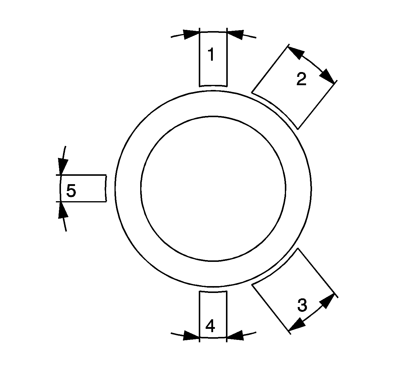
- Set piston ring joints.
| • | Piston compression upper ring in position (1). |
| • | Piston compression lower ring in position (4). |
| • | Interim ring of the piston oil ring rail in position (5), steel band rings of the piston oil ring rail in position (2) and/or (3). |
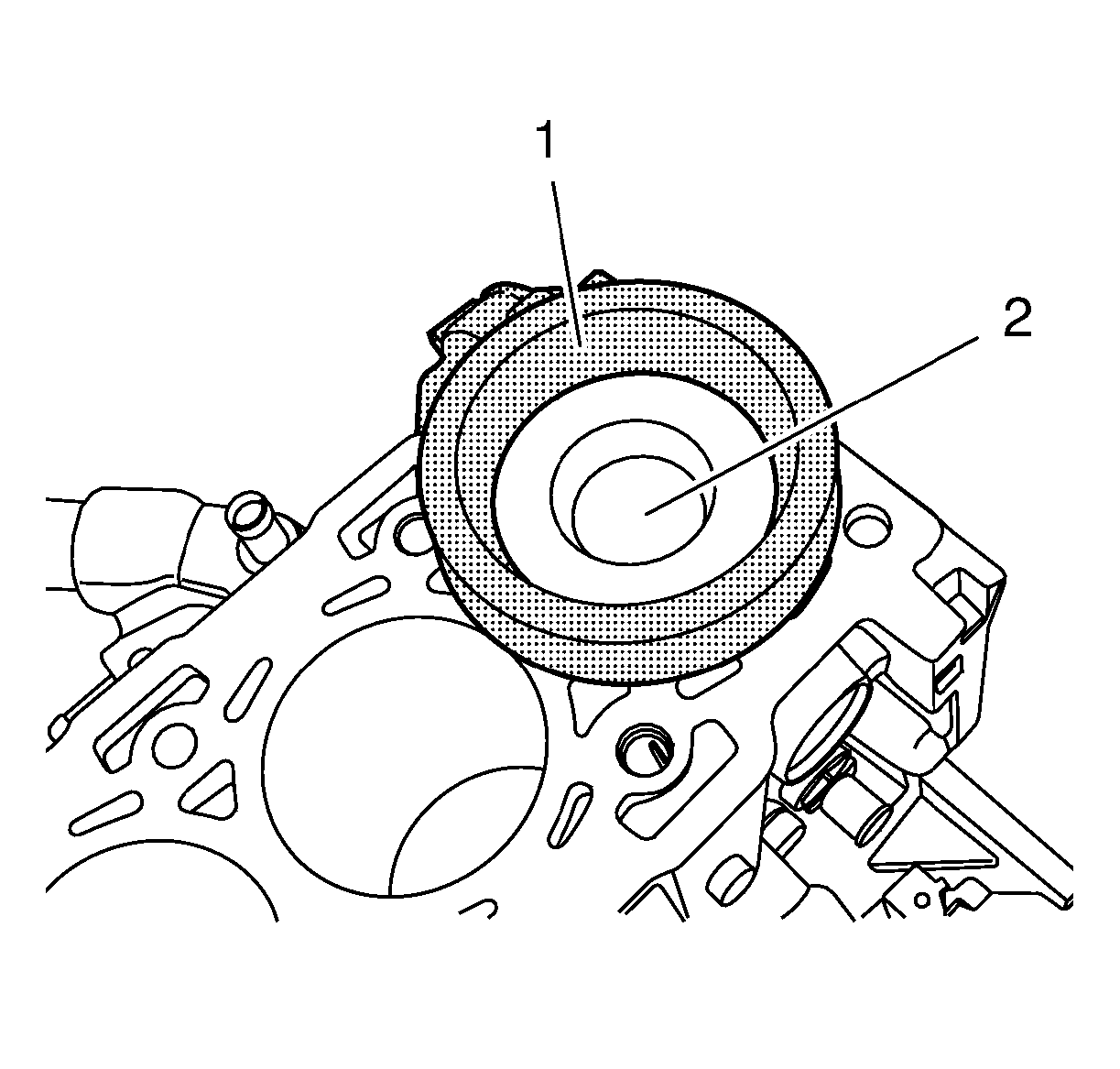
- Lubricate the piston rings, piston (1), inner cylinder bore surface and
EN-48249 compressor
(2) with clean engine oil.
Note: Arrow on piston head points to engine timing side, bead on connecting rod points to transmission side of engine.

- Push the pistons 2 and 3 (1) into the cylinder bore (2).
- Raise the vehicle by its full height.

- Install the connecting rod bearing caps (1) and the connecting rod bearing (3).
- Install 4 NEW connecting rod bearing caps bolts (2) of cylinder 2 and 3 and tighten in 3 passes:
Caution: Refer to Fastener Caution in the Preface section.
| 7.1. | In first pass tighten to
35 N·m (26 lb ft). |
| 7.2. | In second pass tighten to 45 degrees using the
EN-45059 angle sensor
. |
| 7.3. | In third pass tighten to 15 degrees using the
EN-45059 angle sensor
. |
- Turn crankshaft on crankshaft balancer through 180 degrees in direction of rotation of engine.
- Lower the vehicle by its full height.

- Push the pistons 1 and 4 (1) into the cylinder bore (2).
- Raise the vehicle by its full height.

- Install the connecting rod bearing caps (1) and the connecting rod bearing (3).
- Install the 4 connecting rod bearing caps bolts (2) of cylinder 1 and 4 and tighten in 3 passes:
| 13.1. | In first pass tighten to
35 N·m (26 lb ft) |
| 13.2. | In second pass tighten to
45 degrees using the
EN-45059 angle sensor
|
| 13.3. | In third pass tighten to
15 degrees using the
EN-45059 angle sensor
|
- Set the crankshaft in direction of engine rotation to 60 degrees before UDC.
- Install the oil pan. Refer to
Oil Pan Replacement.
- Install the cylinder head. Refer to
Cylinder Head Replacement.


