For 1990-2009 cars only
Removal Procedure
- Remove the throttle body air inlet duct. Refer to Air Cleaner Assembly Replacement in Engine Controls - 3.4L.
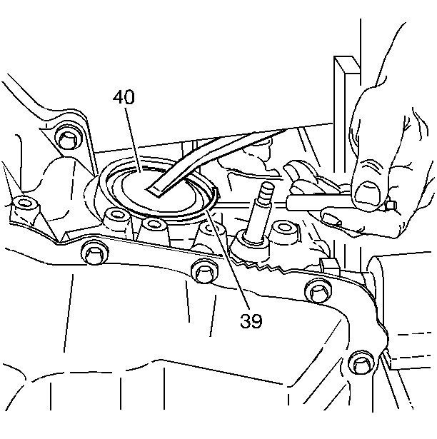
- Use a large flat-bladed tool in order to depress the reverse servo cover (40).
- Use a small flat-bladed tool in order to remove the retaining ring (39).
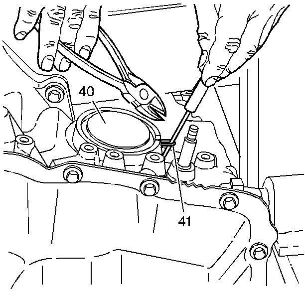
- Use a small flat-bladed tool in order to pull the O-ring seal (41) out through the slot in the case.
- Use side cutting pliers in order to cut the servo cover O-ring seal (41).
- Use a large flat-bladed tool in order to depress the reverse servo cover (40), grasp one end of the cut seal (41) and pull the seal (41) out of the servo cover (40).
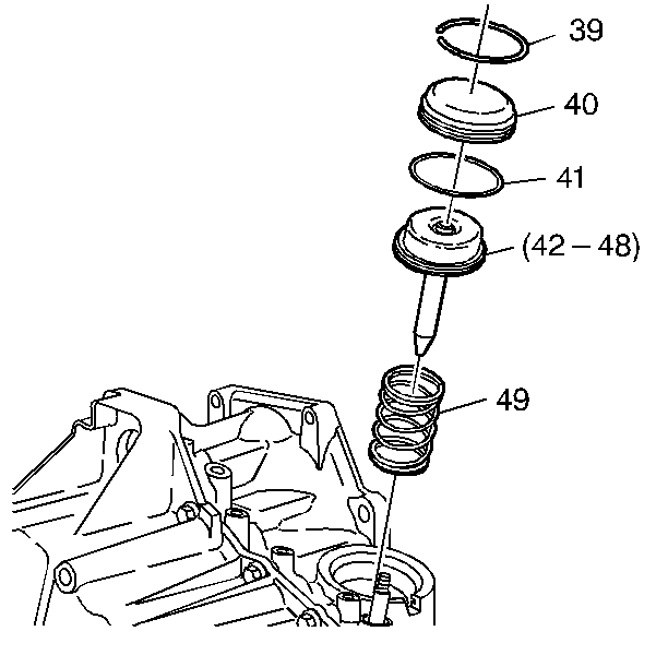
- Remove the reverse servo cover (40).
- Remove the servo assembly (42-48).
- Remove the servo spring (49).


Installation Procedure
- Raise the driver (left) side of the vehicle until it is higher than the passenger (right) differential side. This ensures that the reverse band is in the proper location.
- Install the servo spring (49).
- Install the servo assembly (42-48).
- Install the reverse servo cover (40) with the new O-ring seal (41).
- Install the snap ring (39).
- Install the throttle body air inlet duct. Refer to Air Cleaner Assembly Replacement in Engine Controls - 3.4L.
- Reset the TAP values. Refer to Adapt Function .
Important: Failure to perform the following step may result in no reverse gear due to the servo pin not aligning with the reverse band.

Important: It is recommended that transmission adaptive pressure (TAP) information be reset.
Resetting the TAP values using a scan tool will erase all learned values in all cells. As a result, The ECM, PCM or TCM will need to relearn TAP values. Transmission performance may be affected as new TAP values are learned.