Info - Heating, Ventilation and Air Conditioning (HVAC) - Normal Operational Characteristics

| Subject: | Heating, Ventilation and Air Conditioning (HVAC) -- Normal Operational Characteristics |
| Models: | 1999-2002 Chevrolet Tracker |
Some customers may comment that the HVAC system is not working correctly. When the control is moved to the down or floor (heat) position, air continues to flow from the end vents of the dash.
Step | Action | Yes | No | ||||||
|---|---|---|---|---|---|---|---|---|---|
1 | Was the Function Test performed? | Go to Step 2 | Go to Function Test | ||||||
2 |
Is there airflow through the vent outlets at ambient temperature and no airflow through the heater, defroster and side window defroster outlets? | Go to Step 3 | Go to Step 5 | ||||||
3 |
Is there hot airflow through the heater outlet at the blower high speed, minimum of hot airflow through the defroster and the side window defroster outlets and no airflow at the vent outlets? | Go to Step 4 | Go to Step 5 | ||||||
4 |
Is there hot airflow through the defroster outlet and the side window defroster outlets at the blower at high speed, minimum hot airflow through the heater outlet and no airflow at the vent outlets? | -- | Go to Step 5 | ||||||
5 |
Are the door travel and effort correct? | Go to Step 6 | Go to Step 8 | ||||||
6 | Test the control cable(s) travel by moving the corresponding control at the heater control unit. Is the control cable travel correct? | Go to Step 7 | Go to Step 9 | ||||||
7 | Inspect the control cable(s) attachment at the heater control unit. Repair as necessary. Refer to Control Assembly Replacement. Is the repair complete? | Go to Function Test | -- | ||||||
8 | Repair the affected door at the heater case as necessary. Refer to Heater Case Replacement. Is the repair complete? | Go to Function Test | -- | ||||||
9 | Repair or replace the affected control cable(s) as necessary. Refer to the following:
Is the repair complete? | Go to Function Test | -- |

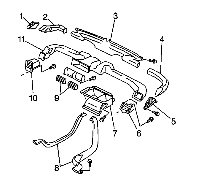
The outlets on each end of the dash (1 and 5) are called the side window air (defroster or demister) outlets. The other outlets (6 and 10) are called Air Outlets (Left Side Vent (10) and Right Side Vent (6)) and face the driver or passenger's outboard shoulder.
It should be noted that the Air Outlet Vents (6 and 10) may be closed with the use of the vent thumb wheel if the driver or passenger desires.
For information purposes, the following chart is provided:
Vent | Vent/Floor | Floor | Floor/Defrost | Defrost | |
|---|---|---|---|---|---|
R. Defroster | 0 | 0 | 5 | 15 | 42.5 |
L. Defroster | 0 | 0 | 5 | 15 | 42.5 |
R. Demister | 0 | 0 | 0 | 2.5 | 7.5 |
L. Demister | 0 | 0 | 0 | 2.5 | 7.5 |
L. Vent | 25 | 20 | 20 | 15 | 0 |
Center Vent | 50 | 30 | 0 | 0 | 0 |
R. Vent | 25 | 20 | 20 | 15 | 0 |
R. Floor | 0 | 15 | 25 | 17.5 | 0 |
L. Floor | 0 | 15 | 25 | 17.5 | 0 |
The above table represents the design intent for the air distribution from the air outlets in each control setting and the percent of the air flow which should be distributed by the system to the outlets. By design, air should be flowing from the Air Outlet Vents (6 and 10) at all times, except for the Defrost mode.
