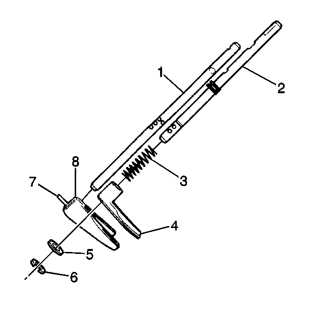
- Place the following components
onto the front drive shift shaft:
| • | The front drive shift shaft C-clip (6) |
| • | The shaft stop washer (5) |
| • | The front drive shift fork spring (3) |
| • | The front drive shift fork (4) |
- Tighten the front drive shift shaft C-clip in order to secure
the above components to the front drive shift shaft.
- Install the reduction shift fork onto the reduction shift shaft.
- Install the reduction shift fork roll pin.
This will secure the reduction shift fork to the reduction shift shaft.
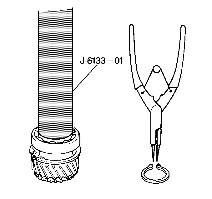
- Use J 6133-A
and a press arbor in order to install
the input gear bearing onto the input gear.
- Install the input gear snap ring onto the input gear.
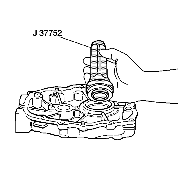
- Use J 37752
in order to install the input gear oil
seal into the front case.
- Apply Loctite® 414 GM P/N 12345493 or equivalent
to the threaded portion of the oil guide bolt.
Notice: Use the correct fastener in the correct location. Replacement fasteners
must be the correct part number for that application. Fasteners requiring
replacement or fasteners requiring the use of thread locking compound or sealant
are identified in the service procedure. Do not use paints, lubricants, or
corrosion inhibitors on fasteners or fastener joint surfaces unless specified.
These coatings affect fastener torque and joint clamping force and may damage
the fastener. Use the correct tightening sequence and specifications when
installing fasteners in order to avoid damage to parts and systems.
- Install the oil
guide in the rear case.
Secure the oil guide with one bolt.
Tighten
Tighten the oil guide bolt to the 10 N·m (89 lb in).
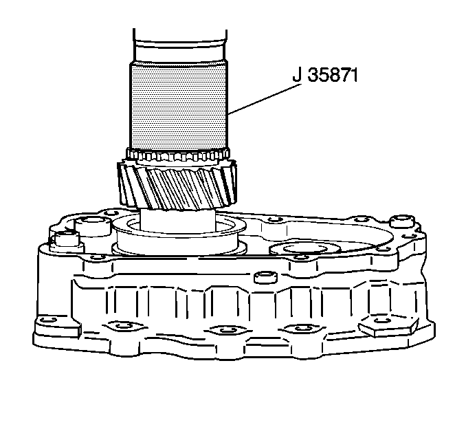
- Use J 35871
and a press arbor in order to install
the input gear into the front case.
- Install the input gear bearing C-clip onto the input gear.
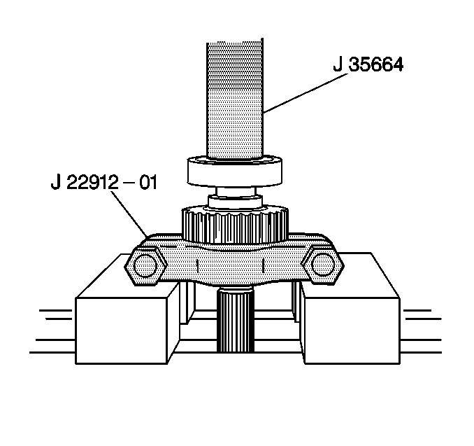
- Use J 35664
with J 22912-O1
and a press arbor in order to install the front output
shaft bearings onto the front output shaft.
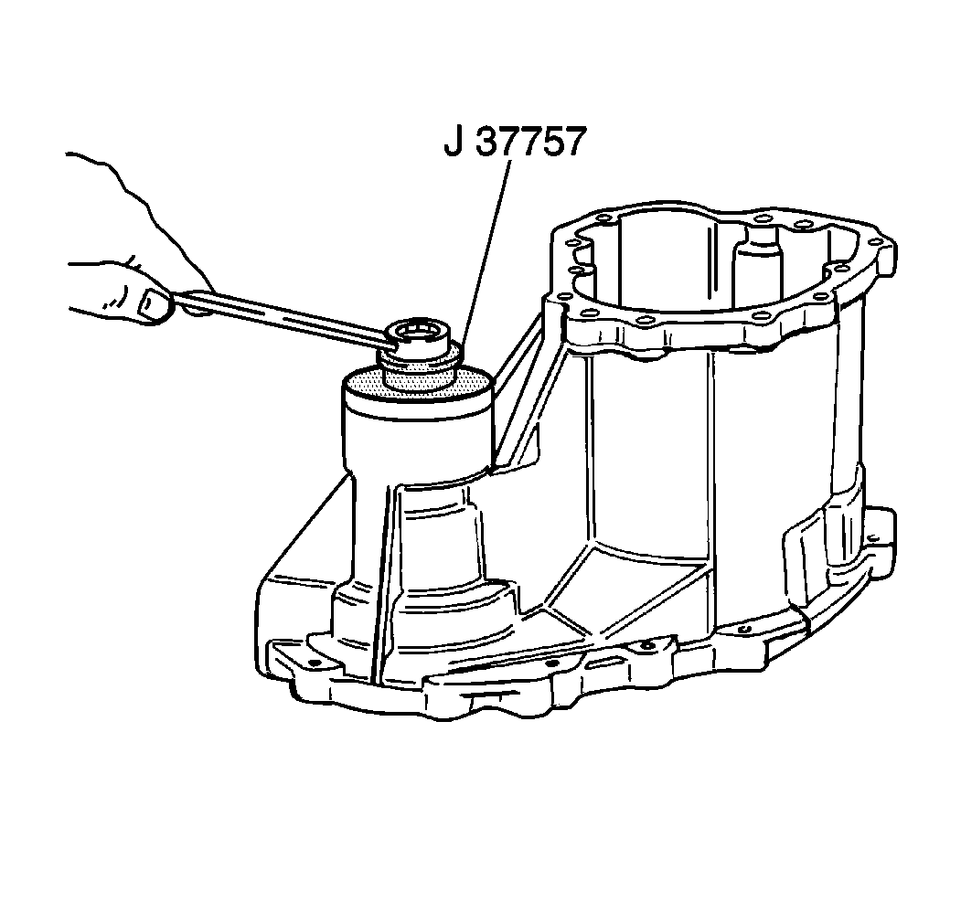
- Use J 37757
in order to install the front output
shaft needle bearing into the center case.
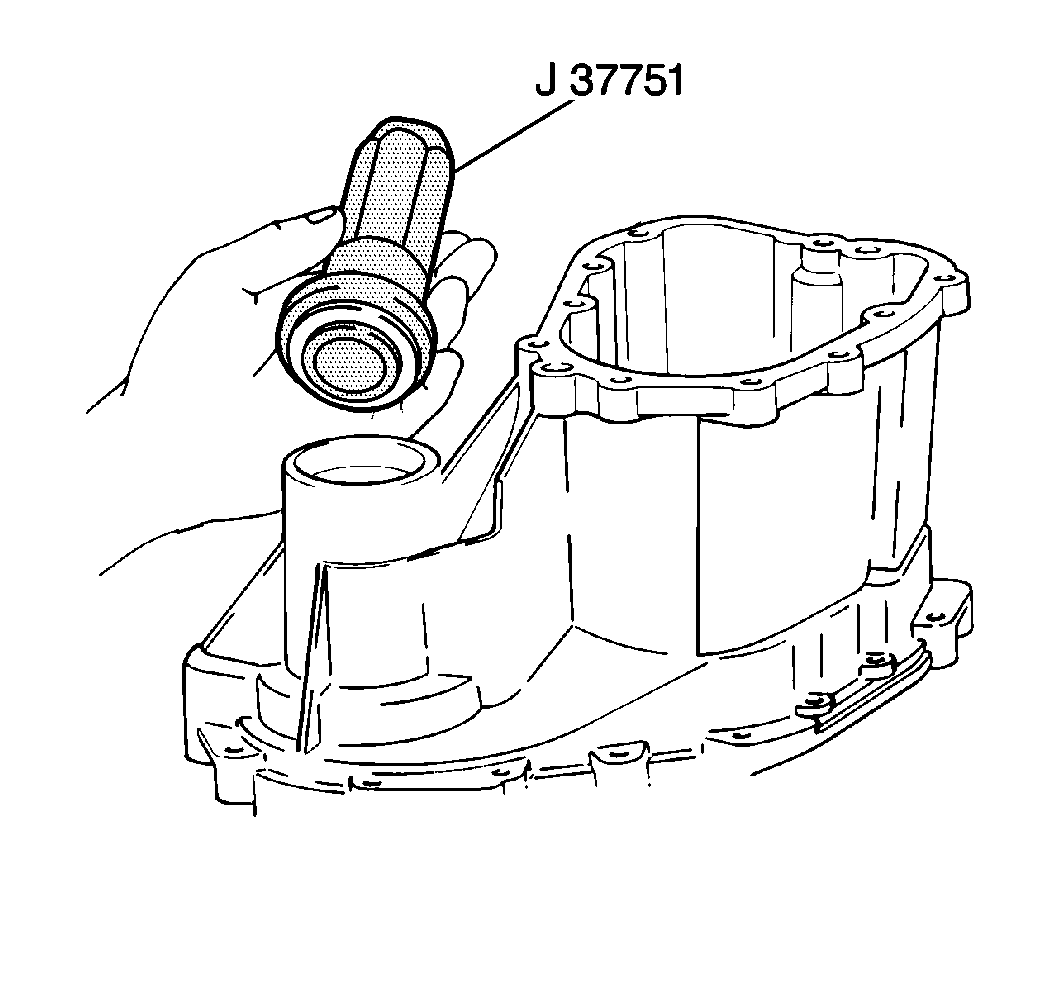
- Use J 37751
in order to install the front output
shaft oil seal into the center case.
- Install the case gutters into the center case.
Secure one case gutter with a bolt, and secure the other gutter with
a screw.
Tighten
Tighten the case gutter bolt to 12 N·m (106 lb in).
- Use a plastic mallet in order to install the front output shaft
into the center case.
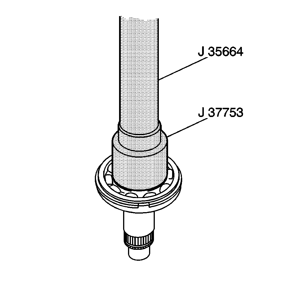
- Use J 37753
with J 35664
and a press arbor in order to install the rear output shaft
front bearing onto the rear output shaft.
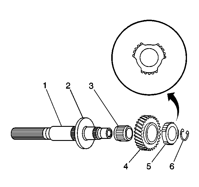
- Install the following
components onto the rear output shaft (1):
| 18.1. | The front bearing (2) |
| 18.2. | The low output gear needle bearing (3) |
| 18.3. | The low output gear (4) |
| 18.4. | The reduction clutch hub (5) |
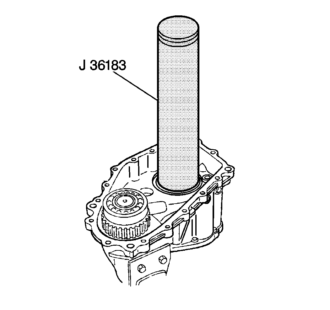
- Use J 36183
in order to install the rear output
shaft into the center case.
- Apply J 36850
to the low output gear needle bearing.
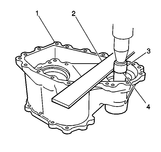
Important: Do NOT press-fit the bearing further than the limit line. If you press
the bearing all the way down to the case bottom, removal of the bearing will
be very difficult.
- Using a press and J 37753
, press-fit the needle bearing into the center case (1). Apply
a straightedge (2) to the top surface of the case and press-fit until
the limit line (4) of J 37753
aligns with the bottom surface of the straightedge.
- Install the reduction hub C-clip (3) onto the rear output
shaft.
- Install the caged needle bearing.
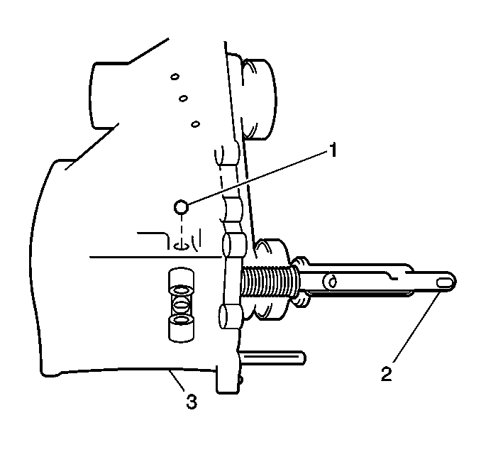
- Install the interlock
ball (1) into the center case passage.
Push against the interlock notch of the front drive shift shaft (2).
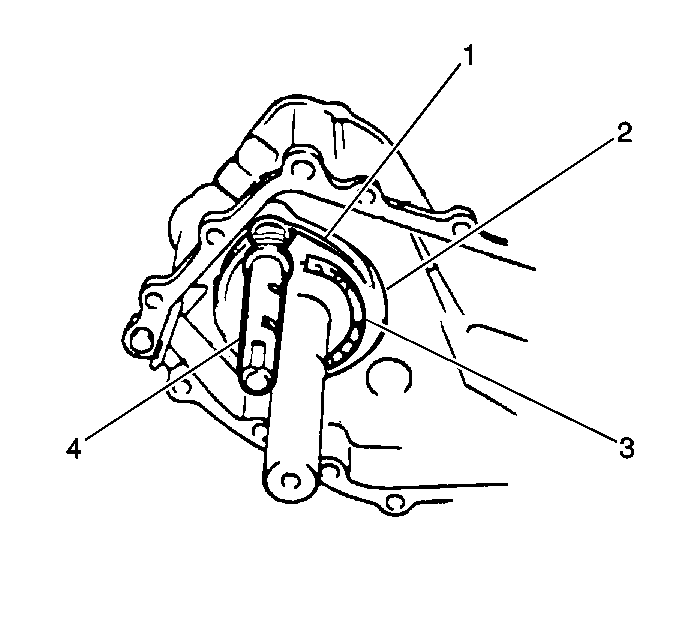
Important: During installation, place the front drive shift shaft at the 4WD position.
- Install the following components onto the rear output shaft, in the
rear of the center case:
| • | The front drive shift shaft (4) |
| • | The front drive shift fork (1) |
| • | The front drive clutch sleeve (2) |
| • | The front drive clutch hub (3) |
- Align the marks on the front drive clutch hub and the sleeve.
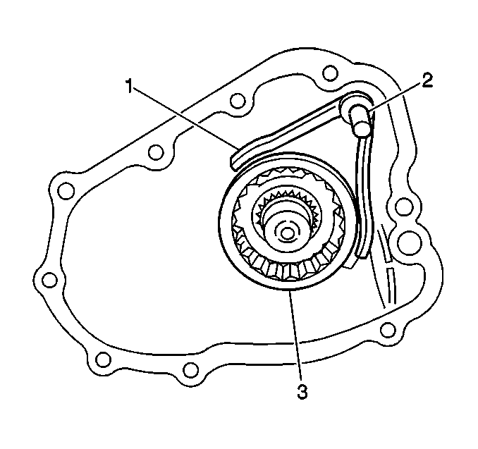
Important: During installation, place the reduction shift shaft at the 4WD position.
- Install the following components onto the rear output shaft, in the
front of the center case.
| • | The reduction shift shaft (2) |
| • | The reduction shift fork (1) |
| • | The reduction clutch sleeve (3) |
- Align the marks on the reduction clutch hub and the sleeve.
- Apply Loctite® 599 RTV silicone sealer or equivalent
to the rubber plug.
- Apply a light coat of Loctite® pipe sealant GM P/N 1052080
or the equivalent to the threaded portion of the 2 locating screws.
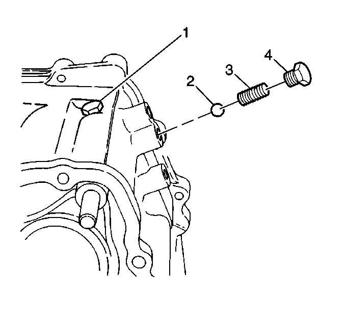
- Install the following
components into the center case:
| • | The 2 locating balls (2) |
| • | The 2 locating springs (3) |
| • | The 2 locating screws (4) |
Tighten
Tighten the locating screws to 26 N·m (19 lb ft).
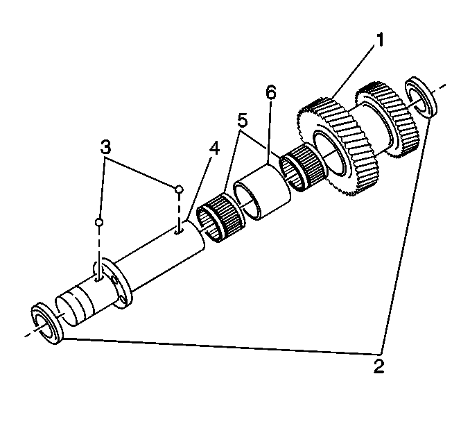
- Install the following
components to the countershaft (4):
| • | The countershaft spacer (6) |
| • | The countershaft needle bearings (5) |
| • | The countershaft washer balls (3) |
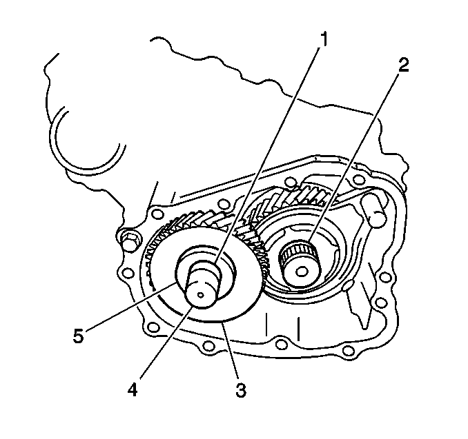
- Install the countershaft assembly (1) into the center case.
- Apply Loctite® 599 RTV silicone sealer or equivalent
to the following surfaces:
| • | The center case mating surfaces |
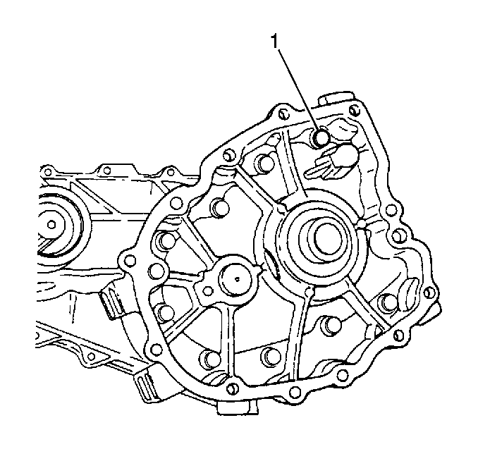
- Install the front case
to the center case.
Secure the front case with 9 bolts (1) .
Tighten
Tighten the front case bolts to 23 N·m (17 lb ft).
- Apply Loctite® 414 GM P/N 12345493 or equivalent
to the threaded portion of the countershaft plate bolt.
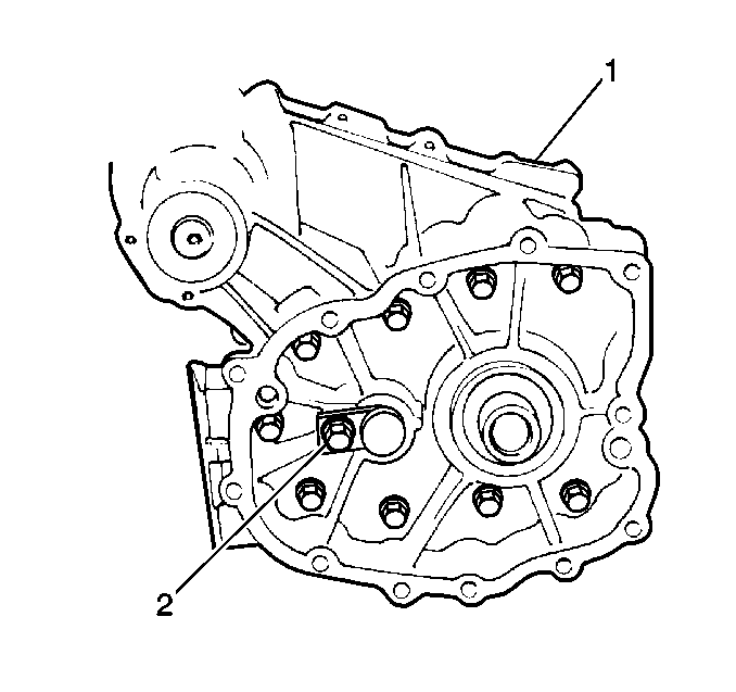
- Install the countershaft
case plate to the front case.
Secure the countershaft case plate with 1 bolt (2).
Tighten
Tighten the countershaft case plate bolt to 23 N·m (17 lb ft).
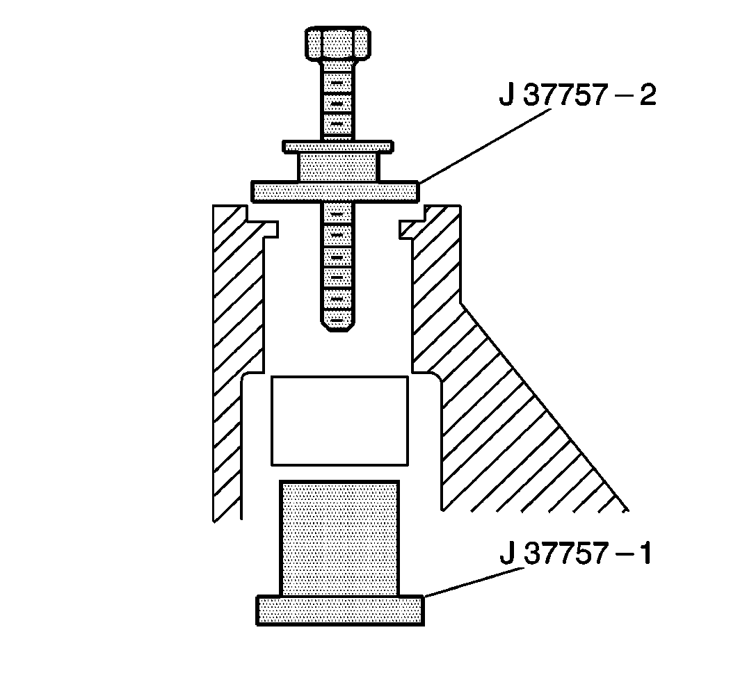
- Use J 37757
in order to install the rear output shaft
needle bearing in the rear case.
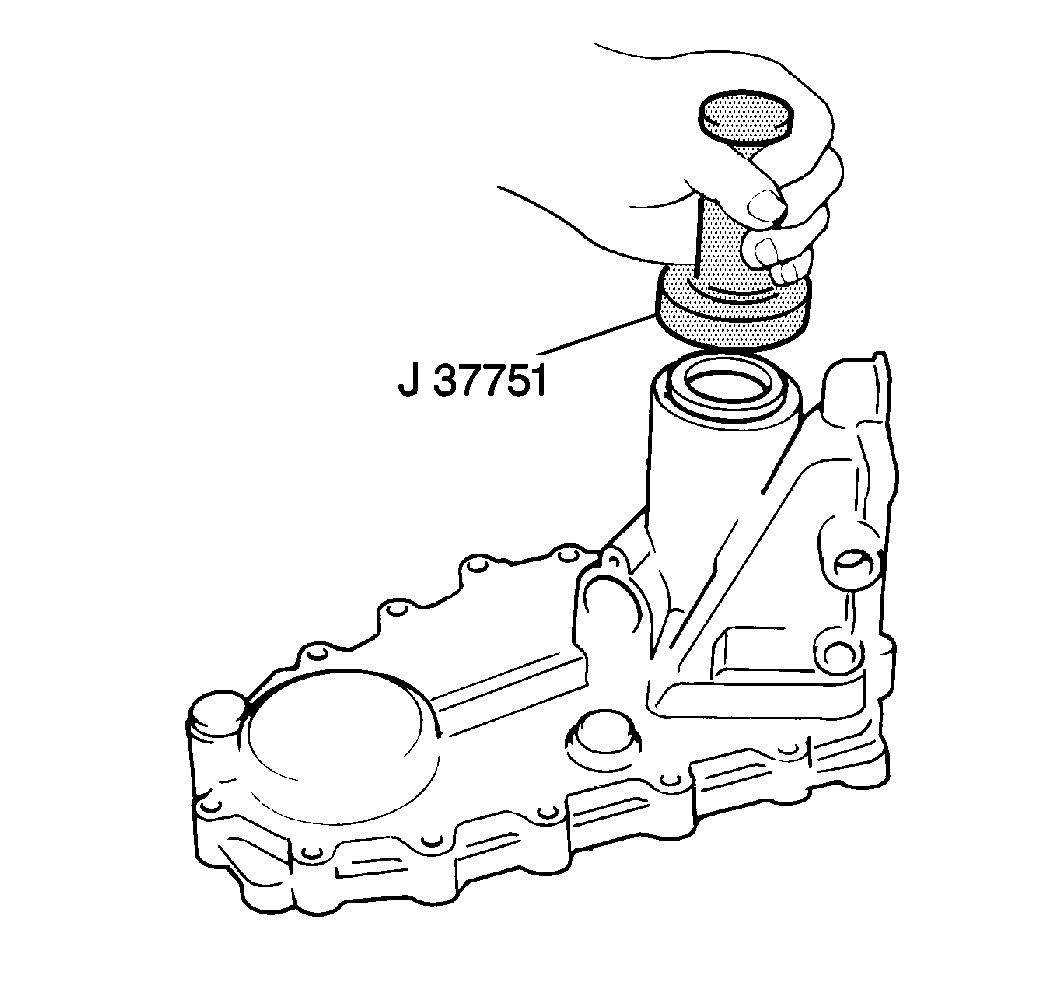
- Use J 37751
in order to install the rear output shaft
oil seal into the rear case.
- Apply J 36850
to the shaft ball in order to retain it in place on the rear output shaft.
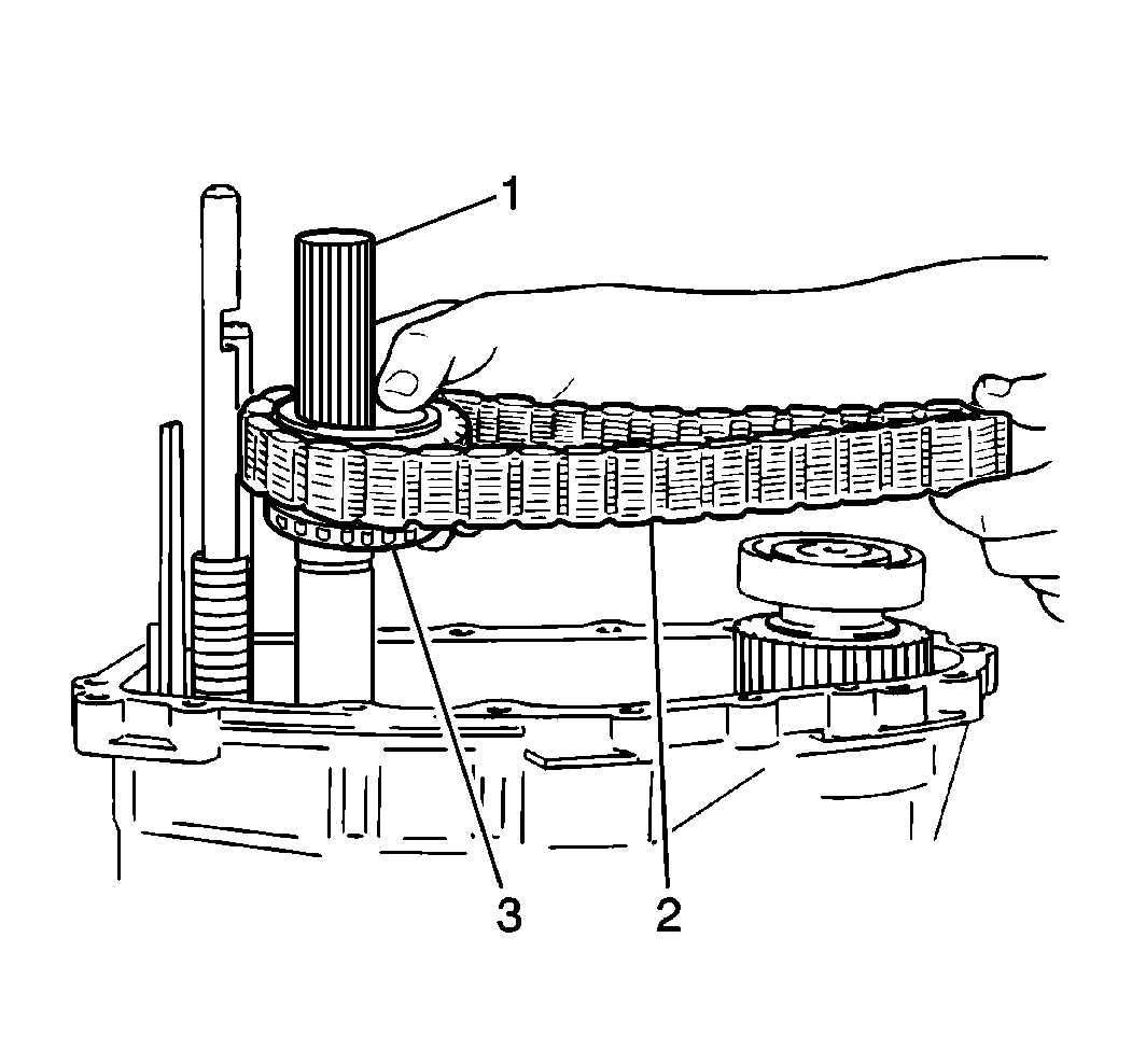
- Install the following
components onto the rear output shaft (1) and onto the front output
shaft:
| • | The rear output shaft washer ball |
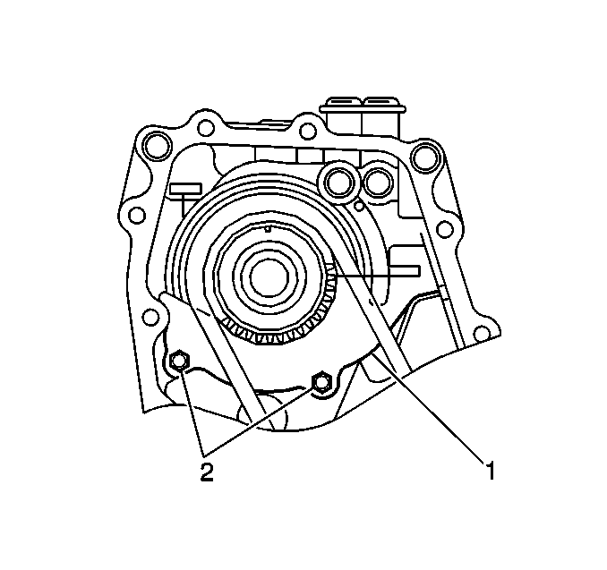
- Install the synchronizer
plate (1) to the front output shaft case.
- Apply Loctite® 414 GM P/N 12345493 or equivalent
to the threaded portion of the 2 screws (2). Secure the synchronizer
plate with the coated screws.
- Apply J 36850
to the drive sprocket needle bearing.
- Install the following components onto the rear output shaft:
| • | The drive sprocket needle bearing |
| • | The drive sprocket bushing |
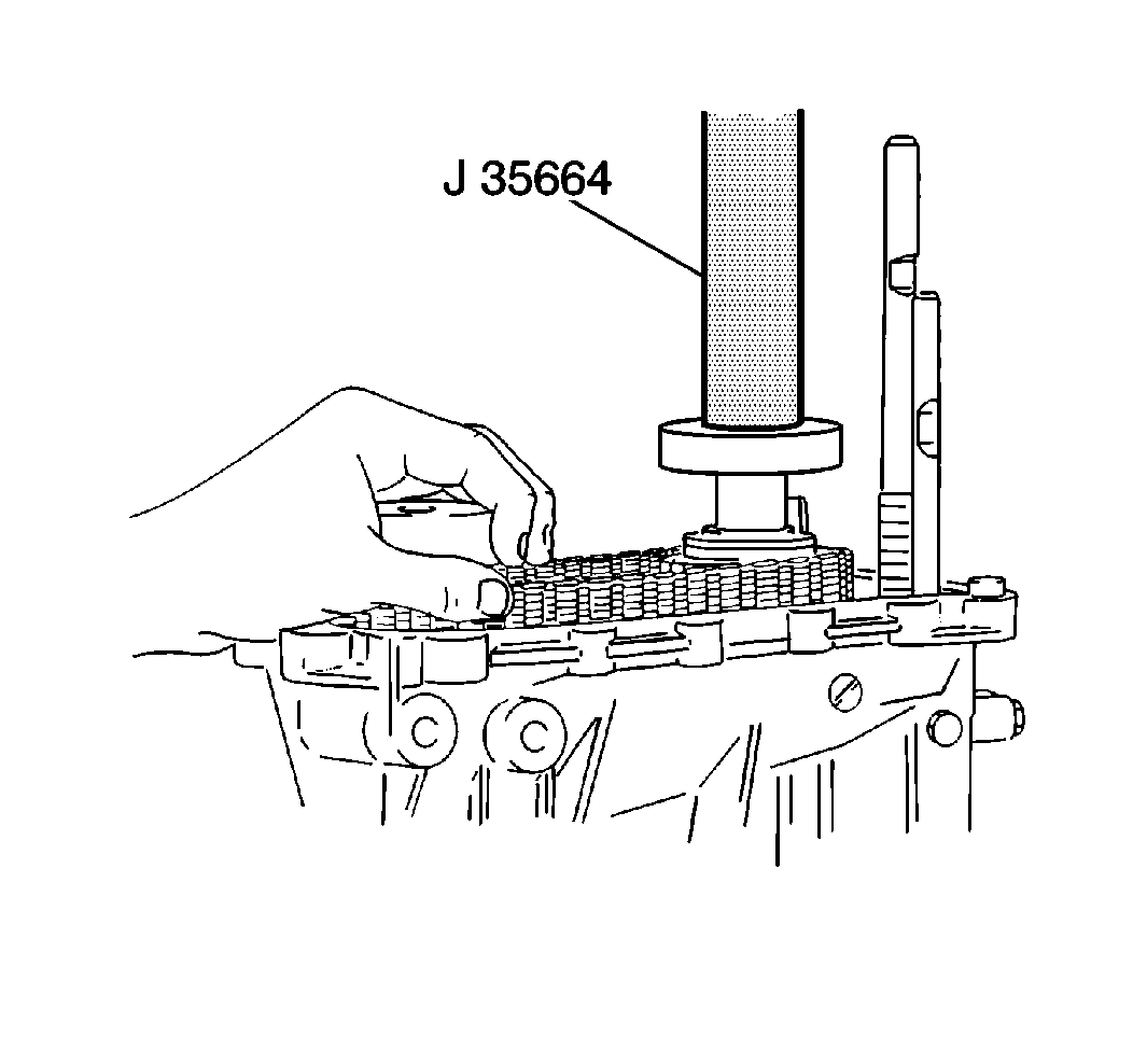
- Use J 35664
in order to install the rear output
shaft rear bearing onto the rear output shaft.
- Install the rear output shaft rear bearing C-clip onto the rear
output shaft.
- Install the speedometer drive gear on the output rear shaft.
Secure the speedometer drive gear with the speedometer drive gear C-clip.
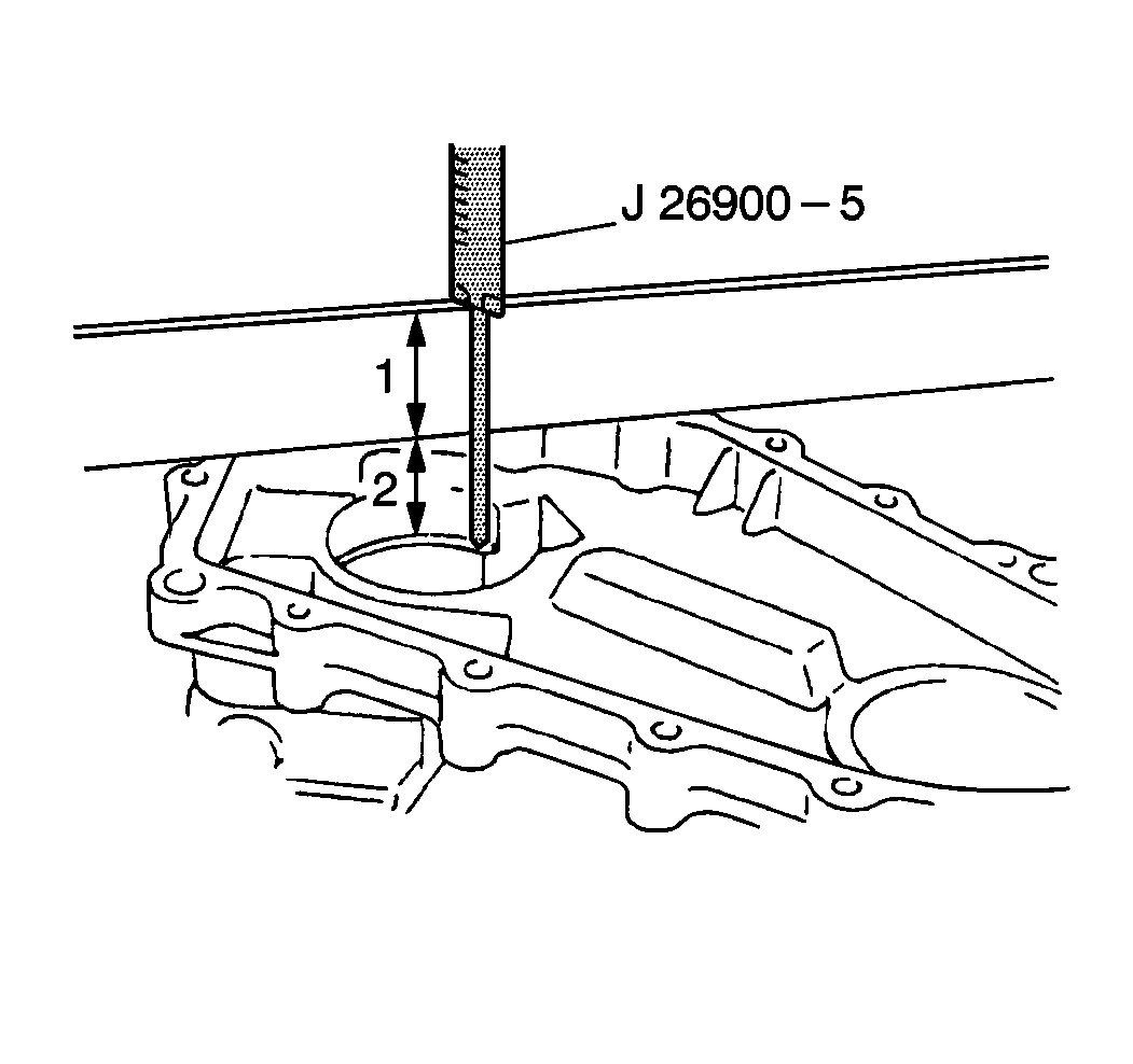
- Use J 26900-5
and a straightedge in order to measure
the rear case bearing bore depth:
| 49.1. | Place the straightedge (1) across the rear case. |
| 49.2. | Measure the bearing bore depth (2) including the width
of the straightedge. |
| 49.3. | Record the measurement. |
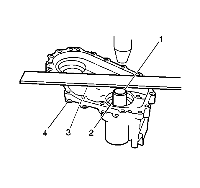
Important: Do NOT press-fit the bearing further than the limit line. If you press
the bearing all the way down to the case bottom, removal of the bearing will
be very difficult.
- Using a press and J 37753
(2), press-fit the needle bearing into the rear case (4).
Apply a straightedge (3) to the top surface of the case and press-fit
until the limit line (1) of J 37753
aligns with the bottom surface of the straightedge.
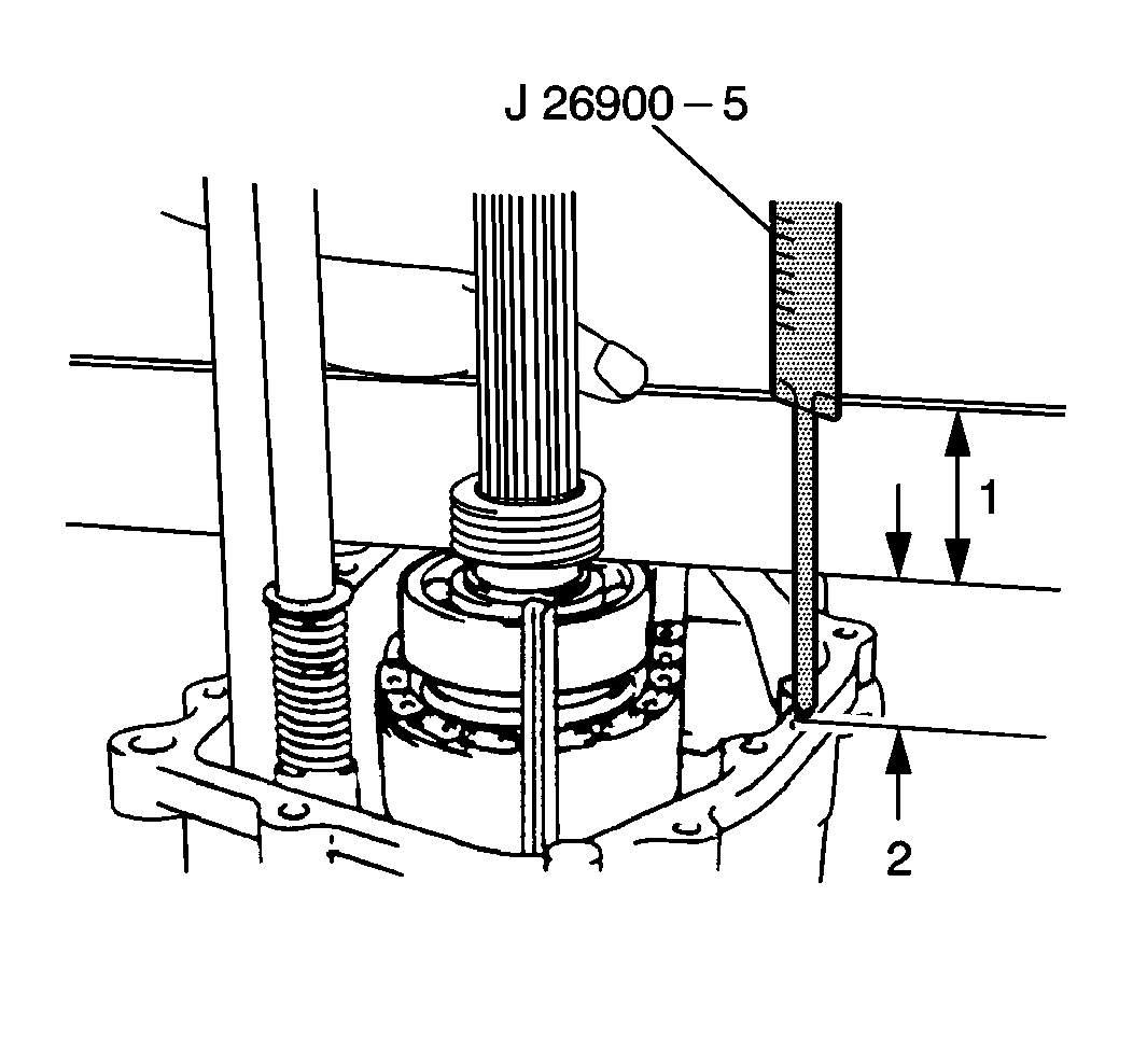
- Use J 26900-5
and a straightedge in order to measure
the height of the rear output shaft rear bearing on the rear output shaft:
| 51.1. | Measure the height of the rear output shaft bearing. |
Include the width of the straightedge.
| 51.2. | Record the measurement. |
Important: No shim is needed if the shim clearance is less than 0.13 mm
(0.0005 in).
- Subtract the height of the bearing on the rear output shaft from the
rear of the case bearing bore depth in order to find the shim clearance.
- Apply J 36850
to the selective shim in order to retain it in place on top
of the rear output shaft rear bearing.
- Install the selective shim to the top of the rear output shaft
rear bearing.
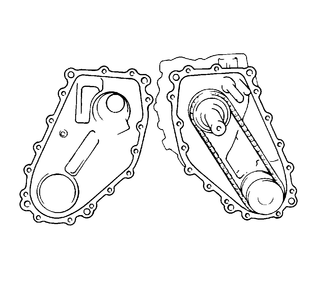
- Apply Loctite® 599
RTV silicone sealer or equivalent to the rear case mating surface.
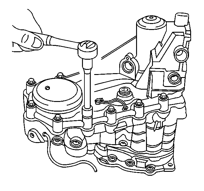
- Install the rear case
to the center case.
Secure the rear case with 15 bolts.
Tighten
Tighten the rear case bolts to 23 N·m (17 lb ft).
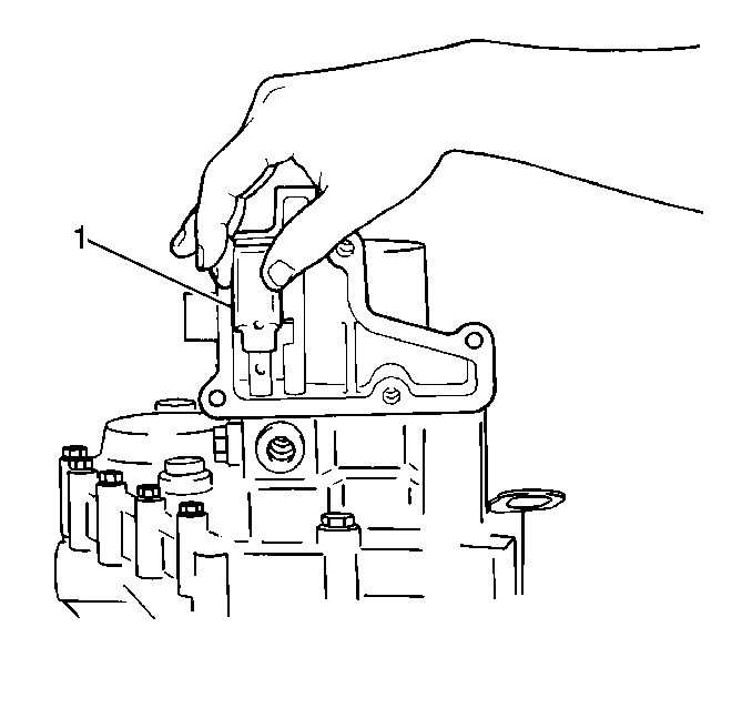
- Install the reduction
shift yoke (1) onto the reduction shift shaft in the rear case.
- Use the reduction shift yoke roll pin in order to secure the reduction
shift yoke to the reduction shift shaft.
- Apply a light coat of Loctite® pipe sealant GM P/N 1052080
or equivalent to the threaded portion of the select return spring bolt.
- Install the following components into the rear case:
| • | The select return ball and washer |
| • | The select return spring |
| • | The select return spring bolt |
Tighten
Tighten the select return spring bolt to 35 N·m (25 lb ft).
- Apply Loctite® 599 RTV silicone sealer or equivalent
to the following surfaces:
| • | The gearshift lever case mating surfaces |
- Install the gearshift lever case to the rear case.
Secure the gearshift lever case with 5 bolts.
Tighten
Tighten the gearshift lever case bolts to 16 N·m (12 lb ft).
- Apply J 36850
to the speedometer driven gear case O-ring.
- Install the speedometer driven gear case.
Secure the speedometer driven gear case with 1 bolt.
Tighten
Tighten the speedometer driven gear case retaining bolt to 10 N·m
(89 lb in).
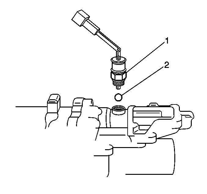
- Inspect the four-wheel
drive switch O-ring for cuts or damage. Replace as necessary.
- Apply J 36850
to the four-wheel drive switch O-ring.
- Install the following components into the rear case:
| • | The four-wheel drive switch (1) |
Tighten
Tighten the four-wheel drive switch to 19 N·m (14 lb ft).
- Inspect the four-wheel drive low switch O-ring for cuts or damage.
Replace as necessary.
- Apply J 36850
to the four-wheel drive low switch O-ring.
- Install the steel ball and the four-wheel drive low switch into
the rear case.
Tighten
Tighten the four-wheel drive low switch to 19 N·m (14 lb ft).


