Removal Procedure
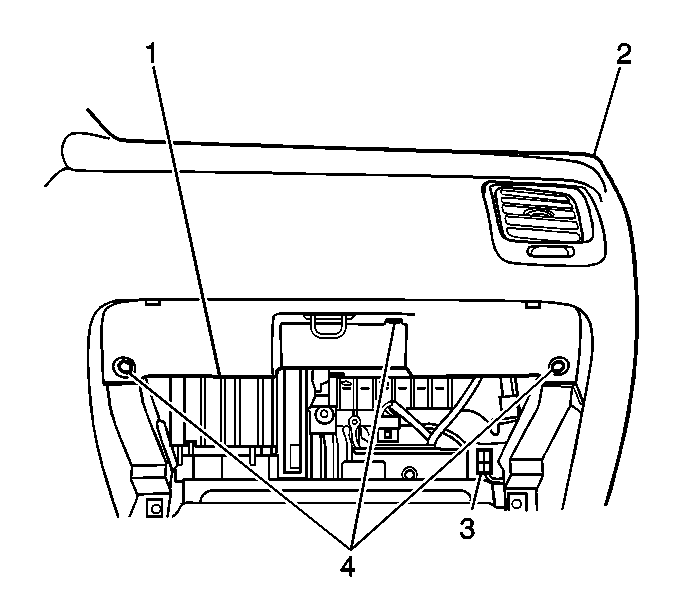
- Disconnect the negative battery cable. Refer
to
Battery Negative Cable Disconnection and Connection
in Engine Electrical.
- Disable the SIR system. Refer to
SIR Disabling and Enabling
and
SIR Disabling and Enabling
in SIR.
- Remove the instrument panel (I/P) compartment. Refer to
Instrument Panel Compartment Replacement
.
- Remove the following components from the I/P assembly (2):
| 4.2. | The I/P compartment trim plate (1) |
- Remove the inflatable restraint I/P module.
Refer to
Inflatable Restraint Instrument Panel Module Replacement
in SIR.
- Remove the front floor console. Refer to
Front Floor Console Replacement
.
- Remove the ashtray lamp bulb. Refer to
Ashtray Lamp Bulb Replacement
in Lighting Systems.
- Remove the radio, if equipped. Refer to
Radio Replacement
in Entertainment.
- Remove the radio opening cover, if equipped. Refer to
Radio Opening Cover Replacement
in Instrument Panel Gages and Console.
- Remove the cigar lighter. Refer to
Cigar Lighter Housing Replacement
.
- Remove the instrument cluster. Refer to
Instrument Cluster Replacement
.
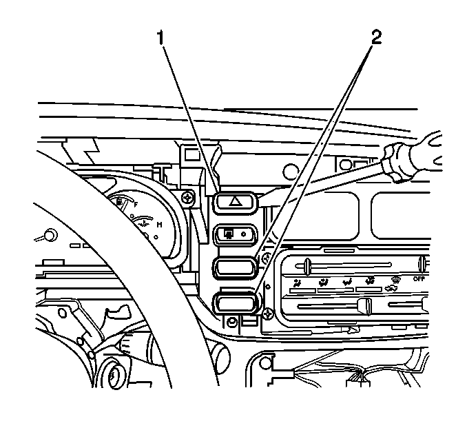
- Using a taped flat-bladed tool, gently pry the 2 I/P accessory
trim plate switch hole covers (2) located below the hazard and defogger switches
from the I/P assembly
- Using a taped flat-bladed tool, gently pry the hazard warning switch (1)
from the I/P assembly.
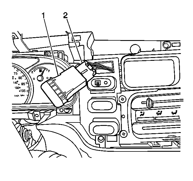
- Disconnect the hazard warning switch electrical
connector (2).
- Remove the switch (1) from the vehicle.

- Using a taped flat-bladed tool, gently pry
the rear window defogger switch (1) from the I/P assembly, if equipped.

- Disconnect the rear window defogger switch
electrical connector (2), if equipped.
- Remove the switch (1) from the vehicle, if equipped.
- Remove the heater control unit. Refer to
Heater and Air Conditioning Control Replacement
in HVAC Systems - Manual.
- Remove the I/P lamp dimmer control.
- Remove the cruise control switch, if equipped. Refer to
Cruise Control Switch Replacement
in Cruise Control.
- Remove the outside remote control rearview mirror switch, if equipped.
Refer to
Power Mirror Switch Replacement
.
- Remove the rear window wiper/washer switch, if equipped. Refer to
Rear Window Wiper and Washer Switch Replacement
in Wipers/Washer
Systems.
- Using a taped flat-bladed tool, gently pry and remove the I/P accessory
trim plate switch hole covers located next to the switches at the left of the I/P
assembly.
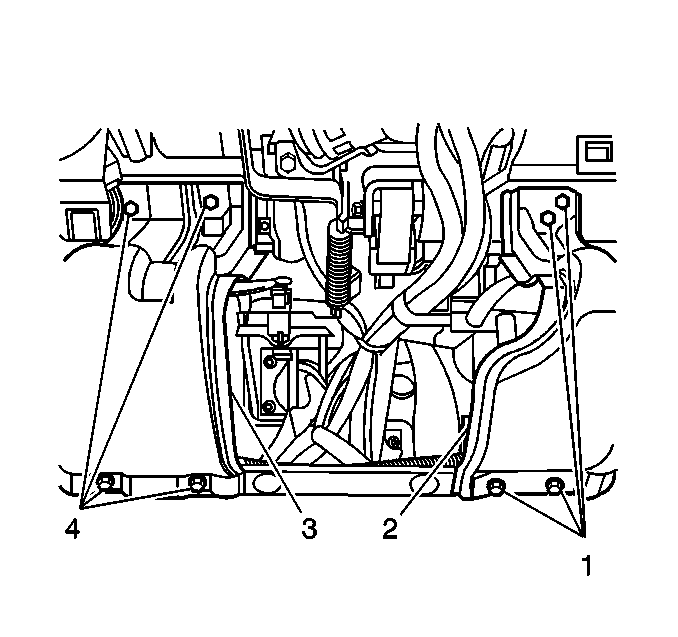
- Remove the following components from the
vehicle:
| 25.1. | The 8 bolts (1 and 4) |
| 25.2. | The I/P drivers knee bolster panels (2 and 3) |
- Remove the steering column. Refer to
Steering Column Replacement
in Steering Wheel and Column.
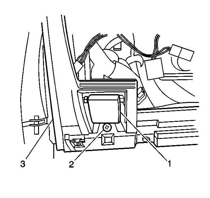
- Remove the screw (2) that retains the hood latch release handle (1)
to the I/P assembly (3).
- Position the hood latch release handle (1) aside in order to gain
the necessary clearance to remove the I/P assembly (3).
- Gently pry loose and remove the windshield side garnish moldings.
- Disconnect the 6 I/P wiring harness electrical connectors from
the junction block.
- Disconnect the radio antenna cable lead from the extension cable in the
junction block area.
- Remove the connector position assurance (CPA) from the inflatable
restraint sensing and diagnostic module (SDM) electrical connector.
- Disconnect the SDM electrical connector.
- Remove the bolt that retains the I/P wiring harness ground wire. The
bolt and the ground wire are located to the left front of the SDM.
- Remove the ambient light sensor. Refer to
Daytime Running Lamp (DRL) Ambient Light Sensor Replacement
in Lighting
Systems.
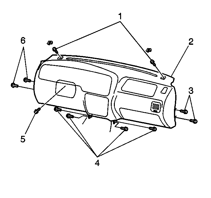
- Remove the 2 bolts (3, 6)
that retain each side of the I/P assembly (2).
- Fold back the floor panel carpet around the center of the I/P assembly (2)
in order to access the 2 center I/P mounting bolts (4) at each side.
- Remove the 2 center I/P mounting bolts (4) that retain
each side of the I/P assembly (2).
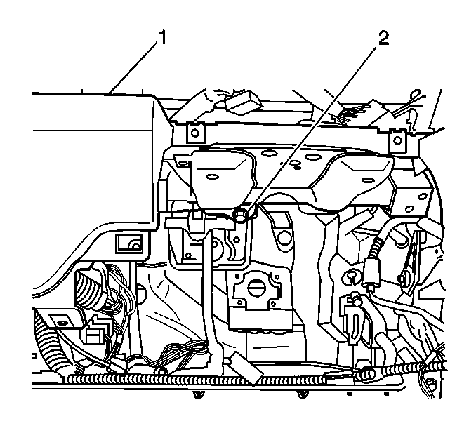
- Remove the bolt (2) that is located
in the steering column area that retains the I/P assembly (1).
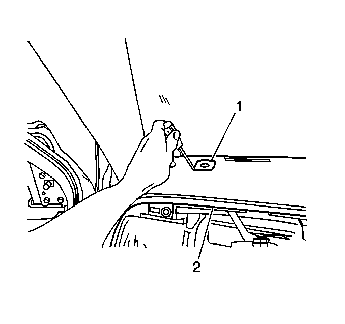
- Remove the left upper I/P bolt trim cover (1)
from the I/P assembly (2).
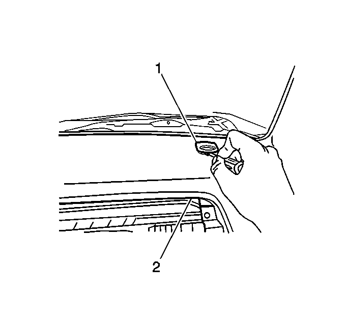
- Remove the right upper I/P bolt trim cover (1)
from the I/P assembly (2).

- Remove the 2 upper I/P mounting bolts (1)
that retain the I/P assembly (2).
- Remove the I/P assembly (2) from the vehicle.
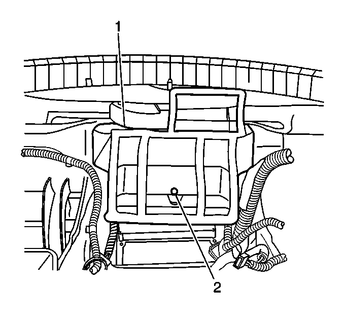
- Remove the following components from the
I/P assembly:
| 44.2. | The air distribution center duct (1) |
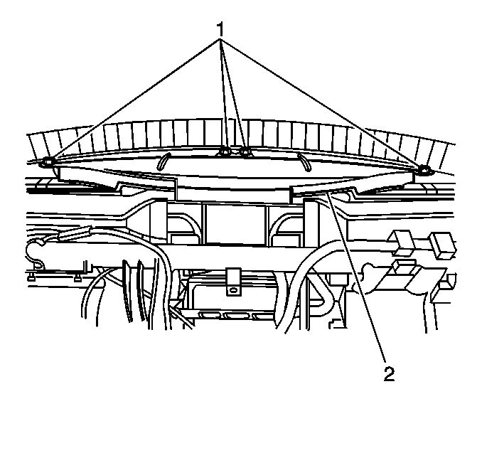
- Remove the following components from the I/P assembly:
| 45.2. | The windshield defroster outlet duct (2) |
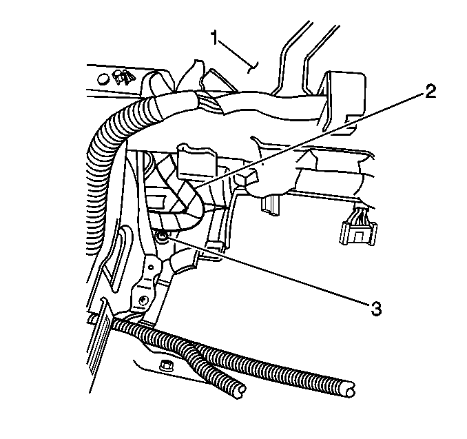
- Remove the screw (3) from the left
side of the rear of the I/P assembly (1) that retains the I/P wiring harness (2).
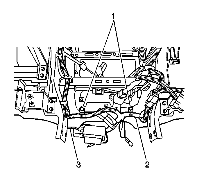
- Remove the 2 screws (1) from
the center of the rear of the I/P assembly (3) that retain the I/P wiring
harness (2).

- Remove the screw (3) from the right
side of the rear of the I/P assembly (1) that retains the I/P wiring harness (2).
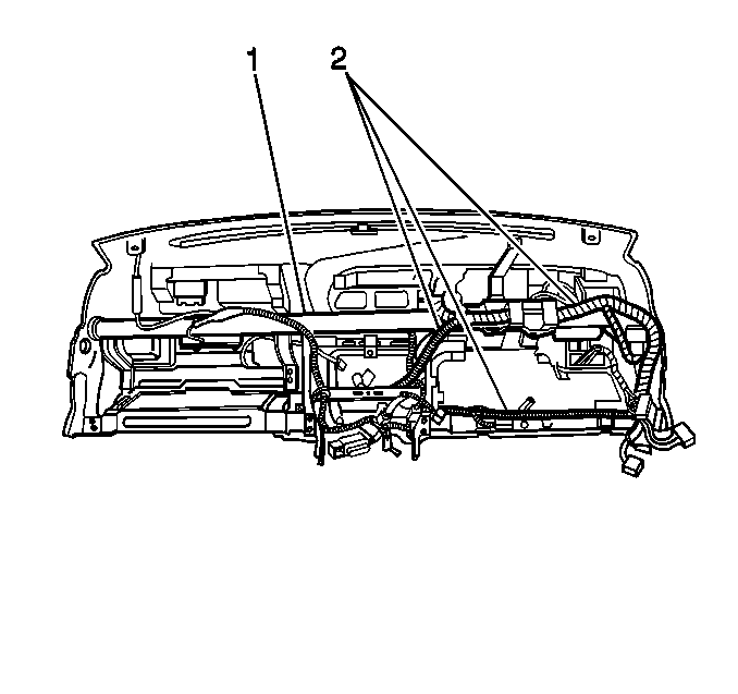
- Release the wiring harness retainers and remove the I/P wiring harness (2)
from the I/P reinforcement (1).
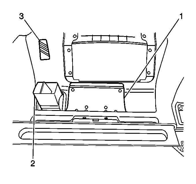
- Remove the following components from the
I/P assembly:
| 50.3. | The I/P reinforcement |
| 50.4. | The left windshield defroster nozzle air deflector (3) |
| 50.6. | The right windshield defroster nozzle air deflector |
| 50.8. | The I/P compartment door reinforcement (1) |
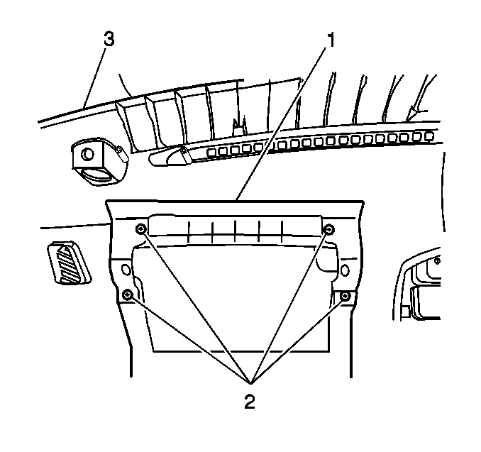
- Remove the following components from the
I/P assembly (3):
| 51.2. | The I/P passengers knee bolster panel (1) |

- Remove the left vent outlet deflector (2)
from the I/P assembly.
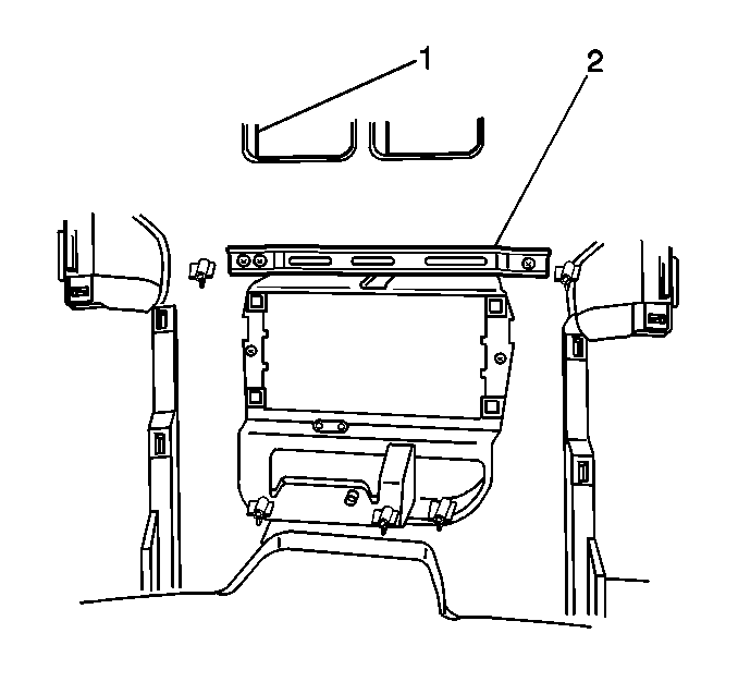
- Remove the following components from the
I/P assembly (1):
| 53.2. | The center I/P bracket (2) |
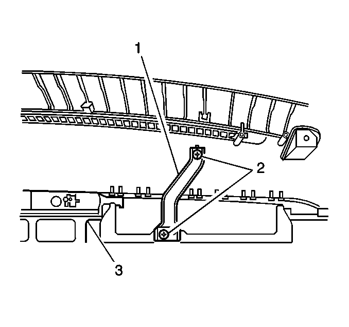
- Remove the following components from the
I/P assembly (3):
| 54.2. | The left I/P bracket (1) |
Installation Procedure

- Install the left I/P bracket (1)
to the I/P assembly (3). Secure the bracket with the 2 screws (2).

- Install the center I/P bracket (2)
to the I/P assembly (1). Secure the bracket with the 3 screws.

- Install the left vent outlet deflector (2)
to the I/P assembly.

- Install the I/P passengers knee bolster
panel (1) to the I/P assembly (3). Secure the panel with the 4 screws (2).

- Install the I/P compartment door reinforcement (1)
to the I/P assembly. Secure the reinforcement with 2 screws.
- Install the right windshield defroster nozzle air deflector to the I/P
assembly. Secure the air deflector with the 3 screws.
- Install the left windshield defroster nozzle air deflector (3)
to the I/P assembly.
Notice: Use the correct fastener in the correct location. Replacement fasteners
must be the correct part number for that application. Fasteners requiring
replacement or fasteners requiring the use of thread locking compound or sealant
are identified in the service procedure. Do not use paints, lubricants, or
corrosion inhibitors on fasteners or fastener joint surfaces unless specified.
These coatings affect fastener torque and joint clamping force and may damage
the fastener. Use the correct tightening sequence and specifications when
installing fasteners in order to avoid damage to parts and systems.
- Install the I/P reinforcement to the I/P assembly. Secure the reinforcement
with the following:
Tighten
Tighten the I/P reinforcement bolts to 23 N·m
(17 lb ft).

- Install the I/P wiring harness (2) to the I/P reinforcement (1).
Secure the harness with the plastic retainers.

- Install the screw (3) to the left
side of the rear of the I/P assembly (1) that retains the I/P wiring harness (2).

- Install the 2 screws (1) to
the center of the rear of the I/P assembly (3) that retain the I/P wiring harness (2).

- Install the screw (3) to the right
side of the rear of the I/P assembly (1) that retains the I/P wiring harness (2).

- Install the heater duct to the I/P assembly.
- Install the windshield defroster outlet duct (2) to the I/P assembly.
Secure the outlet duct with the 4 screws (1).

- Install the air distribution center duct (1)
to the I/P assembly. Secure the center duct with the screw (2).

- Install the I/P assembly (2) to the
vehicle. Secure the I/P with the 2 upper I/P mounting bolts (1). Do
not tighten completely at this time.

- Install the bolt (2) that is located
in the steering column area that retains the I/P assembly (1). Do not tighten
completely at this time.

- Install the 2 center I/P mounting
bolts (4) at each side that retain the I/P assembly (2). Do not tighten
completely at this time.
- Install the 2 bolts (3, 6) at each side that retain the
I/P assembly (2).
Tighten
Tighten all of the I/P mounting bolts to 23 N·m
(17 lb ft).
- Reposition the floor panel carpet around the center of the I/P assembly (2).
- Install the left upper I/P bolt trim cover to the I/P assembly.
- Install the right upper I/P bolt trim cover to the I/P assembly.
- Install the ambient light sensor. Refer to
Daytime Running Lamp (DRL) Ambient Light Sensor Replacement
in Lighting
Systems.

- Install the bolt that retains the I/P wiring harness ground wire. The bolt and
the ground wire are located to the left front of the inflatable restraint sensing
and diagnostic module (SDM).
- Connect the SDM electrical connector. Secure the connector with the CPA.
- Connect the radio antenna cable lead to the extension cable in the junction
block area.
- Connect the 6 I/P wiring harness electrical connectors to the
junction block.
- Install the windshield side garnish moldings.
- Install the hood latch release handle (1) to the I/P assembly (3).
Secure the handle with the screw (2).

- Install the steering column. Refer to
Steering Column Replacement
in Steering Wheel and Column.
- Install the I/P drivers knee bolster panels (2 and 3)
to the vehicle. Secure the bolster panels with the 8 bolts (1 and 4).

- Install the I/P lamp dimmer control.
- Install the outside remote control rearview mirror switch, if equipped.
Refer to
Power Mirror Switch Replacement
.
- Install the cruise control switch, if equipped. Refer to
Cruise Control Switch Replacement
in Cruise Control.
- Install the rear window wiper/washer switch, if equipped. Refer to
Rear Window Wiper and Washer Switch Replacement
in Wipers/Washer
Systems.
- Install the I/P accessory trim plate switch hole covers that are located
next to the switches at the left of the I/P assembly.
- Install the heater control unit. Refer to
Heater and Air Conditioning Control Replacement
in HVAC Systems - Manual.
- Connect the rear window defogger switch electrical connector (2),
if equipped.
- Install the rear window defogger switch (1) to the I/P assembly,
if equipped. Ensure that the retaining tabs are completely engaged.

- Connect the hazard warning switch electrical
connector (2).
- Install the hazard warning switch (1) to the I/P assembly. Ensure
that the retaining tabs are completely engaged.
- Install the 2 I/P accessory trim plate switch hole covers that
are located below the hazard and defogger switches to the I/P assembly.
- Install the instrument cluster. Refer to
Instrument Cluster Replacement
.
- Install the cigar lighter. Refer to
Cigar Lighter Housing Replacement
.
- Install the radio, if removed. Refer to
Radio Replacement
in Entertainment.
- Install the radio opening cover, if removed. Refer to
Radio Opening Cover Replacement
in Instrument Panel, Gages, and Console.
- Install the ashtray lamp bulb. Refer to
Ashtray Lamp Bulb Replacement
in Lighting Systems.
- Install the front floor console. Refer to
Front Floor Console Replacement
.
- Install the inflatable restraint I/P module. Refer to
Inflatable Restraint Instrument Panel Module Replacement
in SIR.

- Install the I/P compartment trim plate (1)
to the I/P assembly (2). Secure the trim plate with the 3 screws (3).
- Install the I/P compartment. Refer to
Instrument Panel Compartment Replacement
.
- Enable the SIR System. Refer to
SIR Disabling and Enabling
and
SIR Disabling and Enabling
in SIR.
- Connect the negative battery cable. Refer to
Battery Negative Cable Disconnection and Connection
in Engine Electrical.


