Removal Procedure
- Ensure the front tires and wheels are in the straight ahead position.
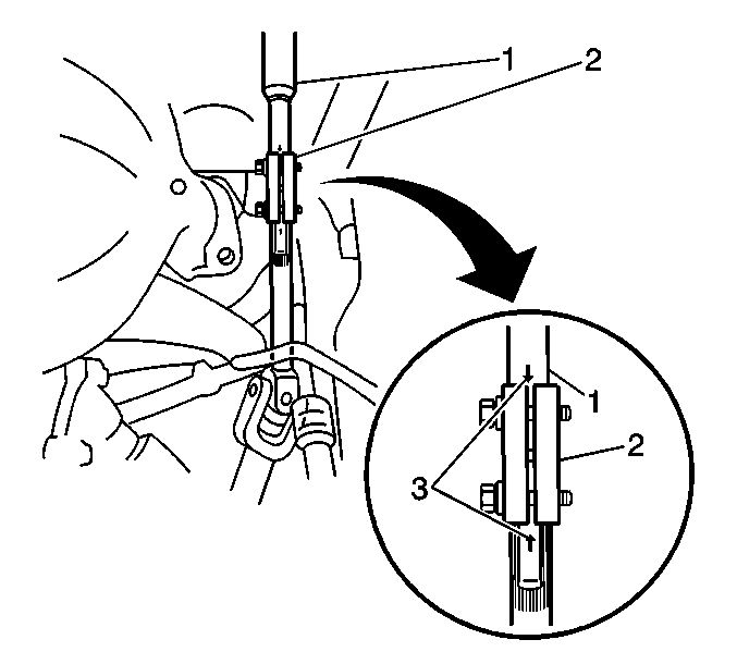
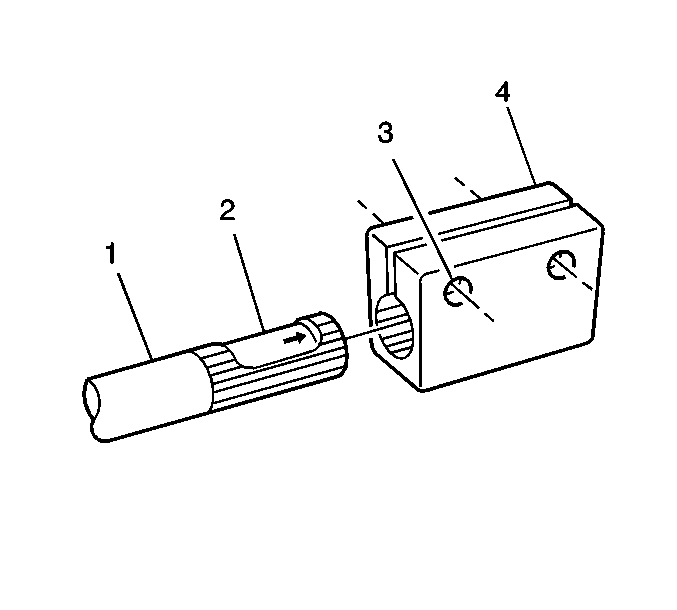
- Rotate the steering wheel to the left in order to position the opening in the steering shaft coupling (2) in the vertical position.
- Using paint, place match marks (3) on the steering column shaft (1) and the lower steering shaft in order to mark the location of the opening in the steering shaft coupling (2).
- Remove the key from the ignition switch.
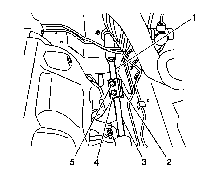
- Turn the steering wheel to the left in order to lock the steering column and allow access to the steering shaft coupling bolts (4,5).
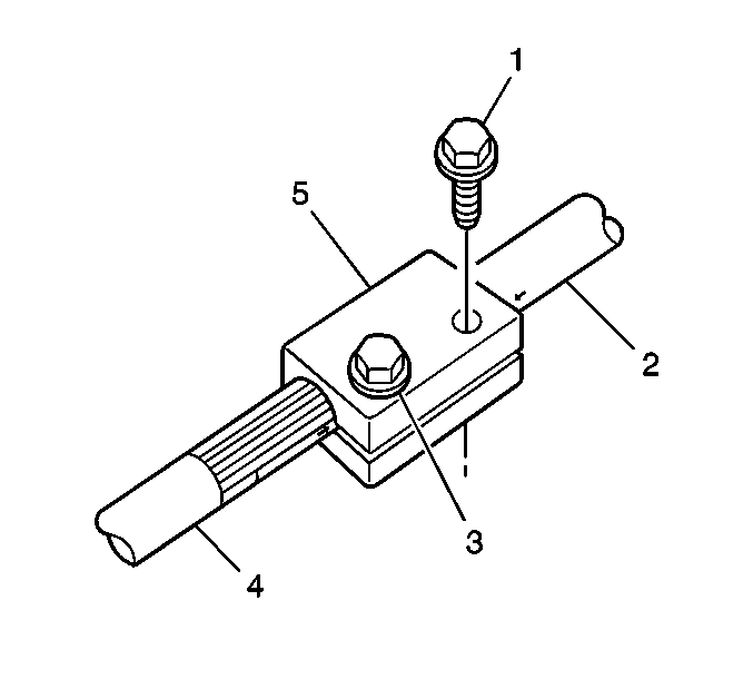
- Remove the 2 bolts (1,3) from the steering shaft coupling (5).
- Use a plastic hammer in order to tap the steering shaft coupling (2) onto the lower steering shaft (3).
- Remove the steering shaft coupling from the lower steering shaft.
Notice: The steering column must be in the LOCK position before disconnecting
the following components:
• The steering column • The steering shaft coupling • The intermediate shaft • The lower steering shaft
Installation Procedure
- Ensure the steering wheel and the front tires and wheels have not moved since the removal of the steering shaft coupling.
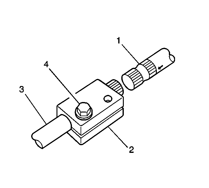
- Align the opening in the steering shaft coupling (4) with the match mark on the flat surface of the lower steering shaft (2). Slide the steering shaft coupling onto the lower steering shaft.
- Install the lower steering column bolt into the lower bolt hole (3).
- Align the opening in the steering shaft coupling (2) with the match mark on the steering column shaft (1). Use a plastic hammer in order to tap the steering shaft coupling onto the steering column shaft.
- Install the upper bolt (1).
- Tighten the upper bolt (1) to 25 N·m (18 lb ft).
- Tighten the lower bolt (3) to 25 N·m (18 lb ft).
Important: DO NOT tighten the lower coupling bolt before tightening the upper coupling bolt.

Notice: Use the correct fastener in the correct location. Replacement fasteners must be the correct part number for that application. Fasteners requiring replacement or fasteners requiring the use of thread locking compound or sealant are identified in the service procedure. Do not use paints, lubricants, or corrosion inhibitors on fasteners or fastener joint surfaces unless specified. These coatings affect fastener torque and joint clamping force and may damage the fastener. Use the correct tightening sequence and specifications when installing fasteners in order to avoid damage to parts and systems.

Tighten
