For 1990-2009 cars only
- Inspect the valve.
- Inspect the valve or stem for abrasion, burn, or bending. Replace as necessary.
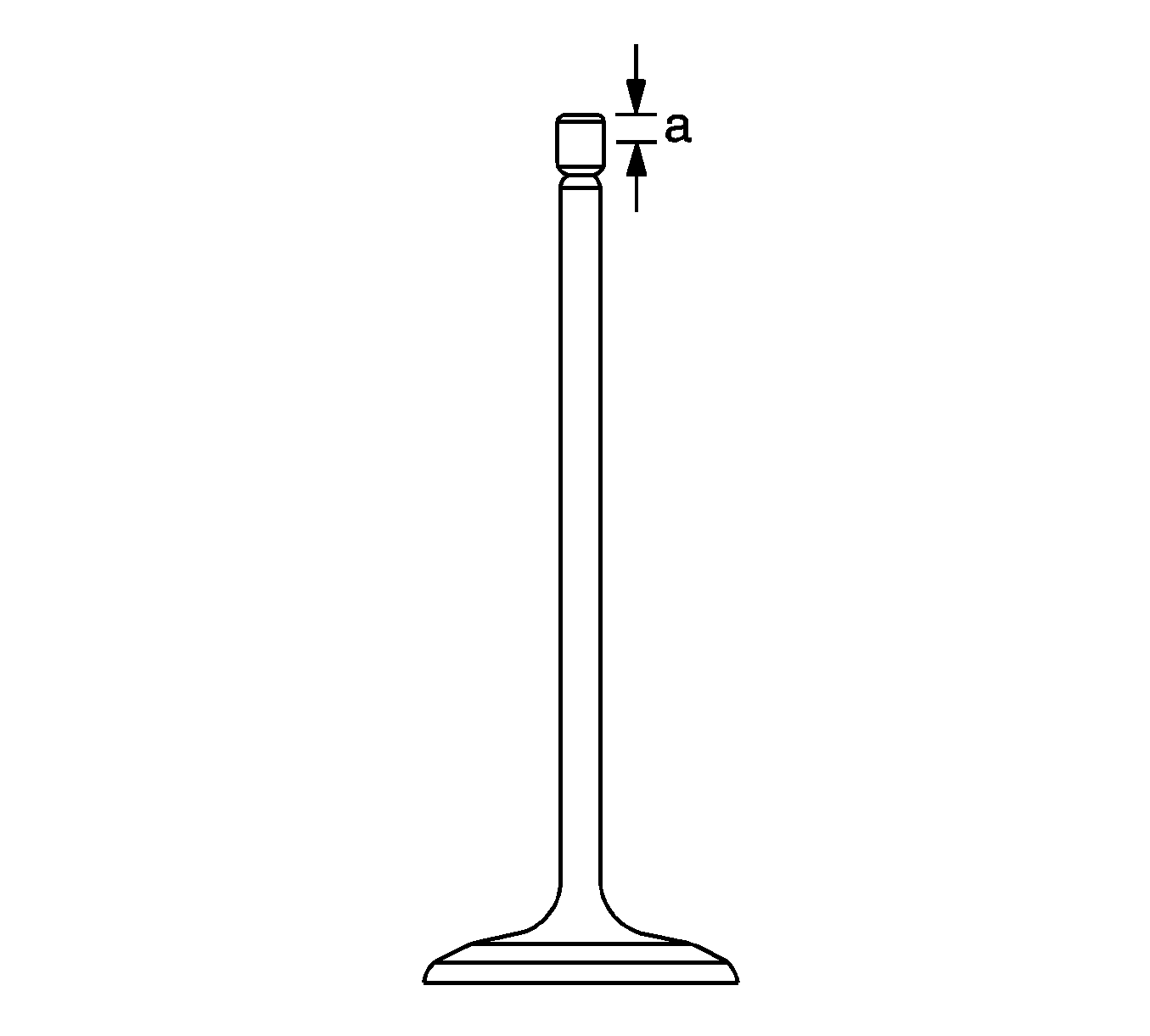
- Inspect the edge of each valve for abrasion. Some uneven abrasion would be made on the edge because the rocker arm gets contacted at this surface when operating.
- Repair the section within 0.05 mm (0.002 in) as required, or replace the valve if more modification is required (a).
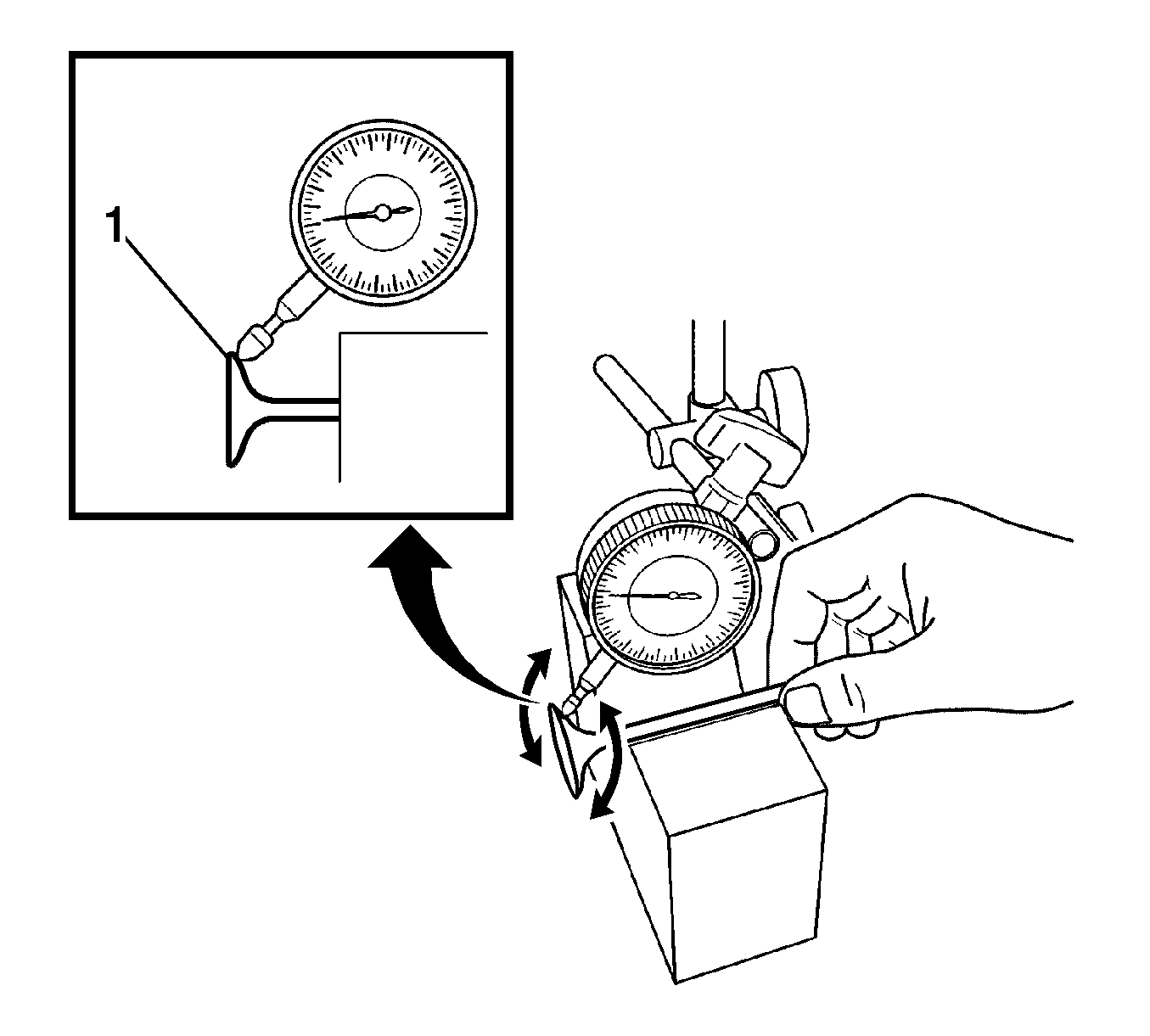
- Measure the deviation to the rotating direction (1) using a dial gage and the V block by turning the valve slowly.
- If the measured valve exceeds the limit, replace the valve.
- Clean the valve and the valve seat. Apply red stamping ink thinly to the contacting surface of the valve seat. Inspect the fitting after installing the valve unit.
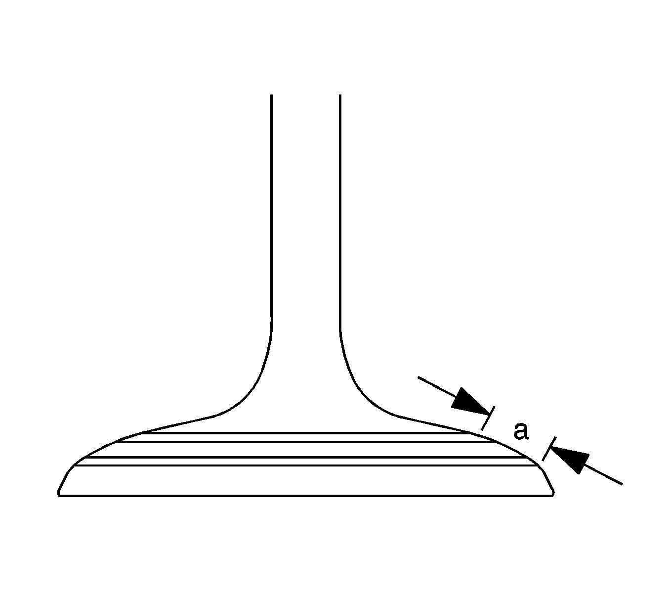
- Inspect the contact width (a) on the surface of the valve seat.
- Repair by grinding and cutting off the valve seat. Lap it if the contacting width is uneven or out of the specified range (1).
- When applying a seat cutter, use one with a smaller angle first. Increase the angle of the cutter up to the light and final modification of the contact. Finish the contact surface with the cutter at 45 degrees.
- Lap both intake (1) and the exhaust (2) sides in 2 stages:
Specification
The deviation limit of the valve head to the rotating direction is within 0.08 mm (0.0031 in).
Warning: Refer to Safety Glasses Warning in the Preface section.
Specifications
| • | The intake is 1.46-1.66 mm (0.0575-0.0654 in). |
| • | The exhaust is 1.46-1.66 mm (0.0575-0.0654 in). |
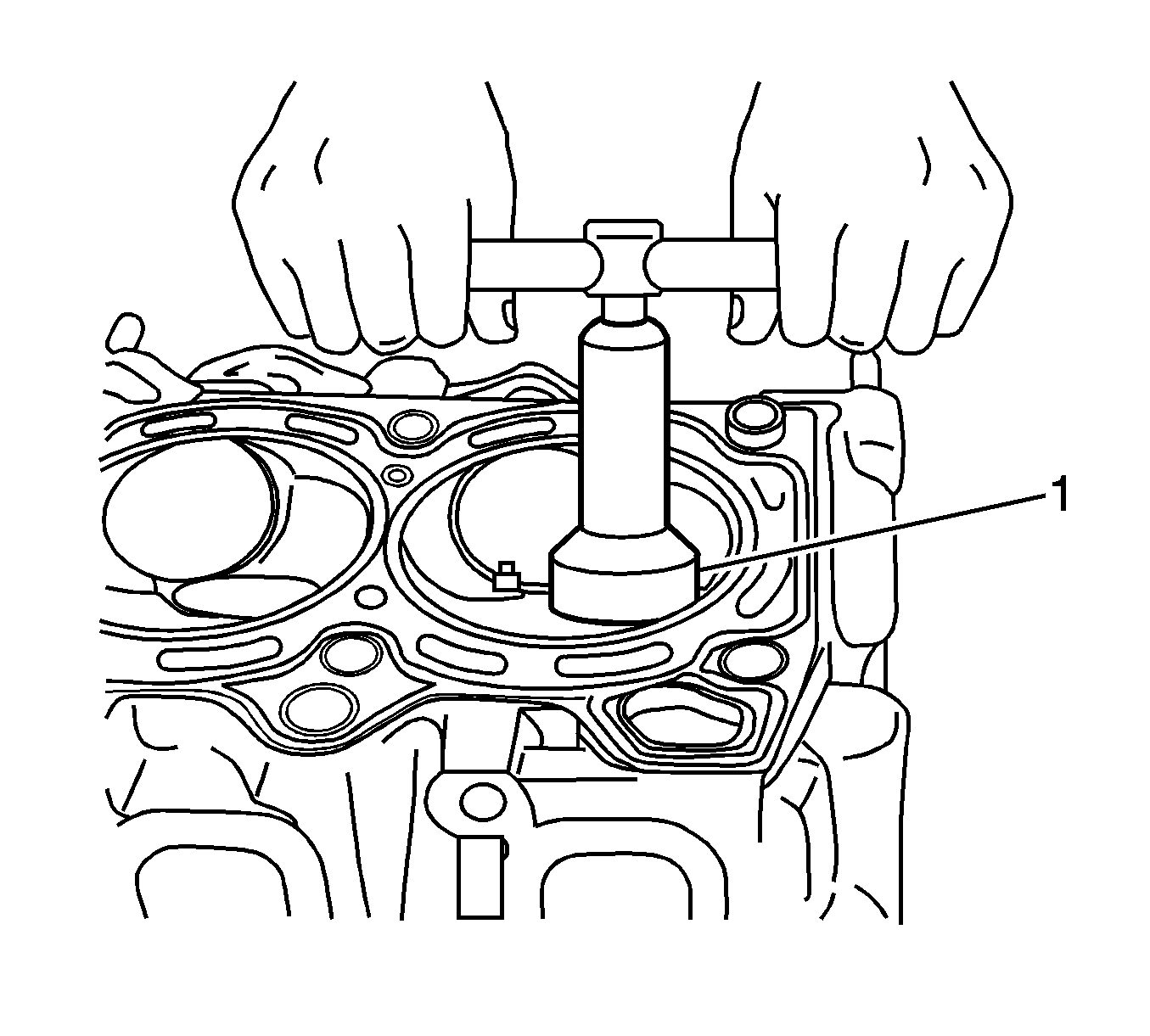
Note: Upon cutting, take care of the contact width. Finish the cutting by gradually reducing the power so that there is no cutting mark on the surface.
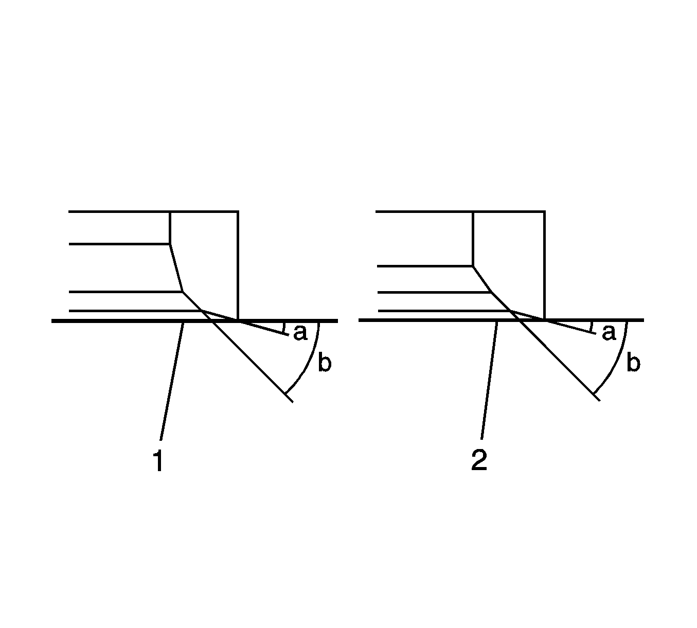
| • | First stage - normal lap |
| • | Second stage - fine lap |
