For 1990-2009 cars only
Removal Procedure
- Relieve the fuel system pressure. Refer to Fuel Pressure Relief.
- Disconnect the negative battery cable.
- Remove the air filter, resonator, and the snorkel assembly. Refer to Air Cleaner Assembly Replacement.
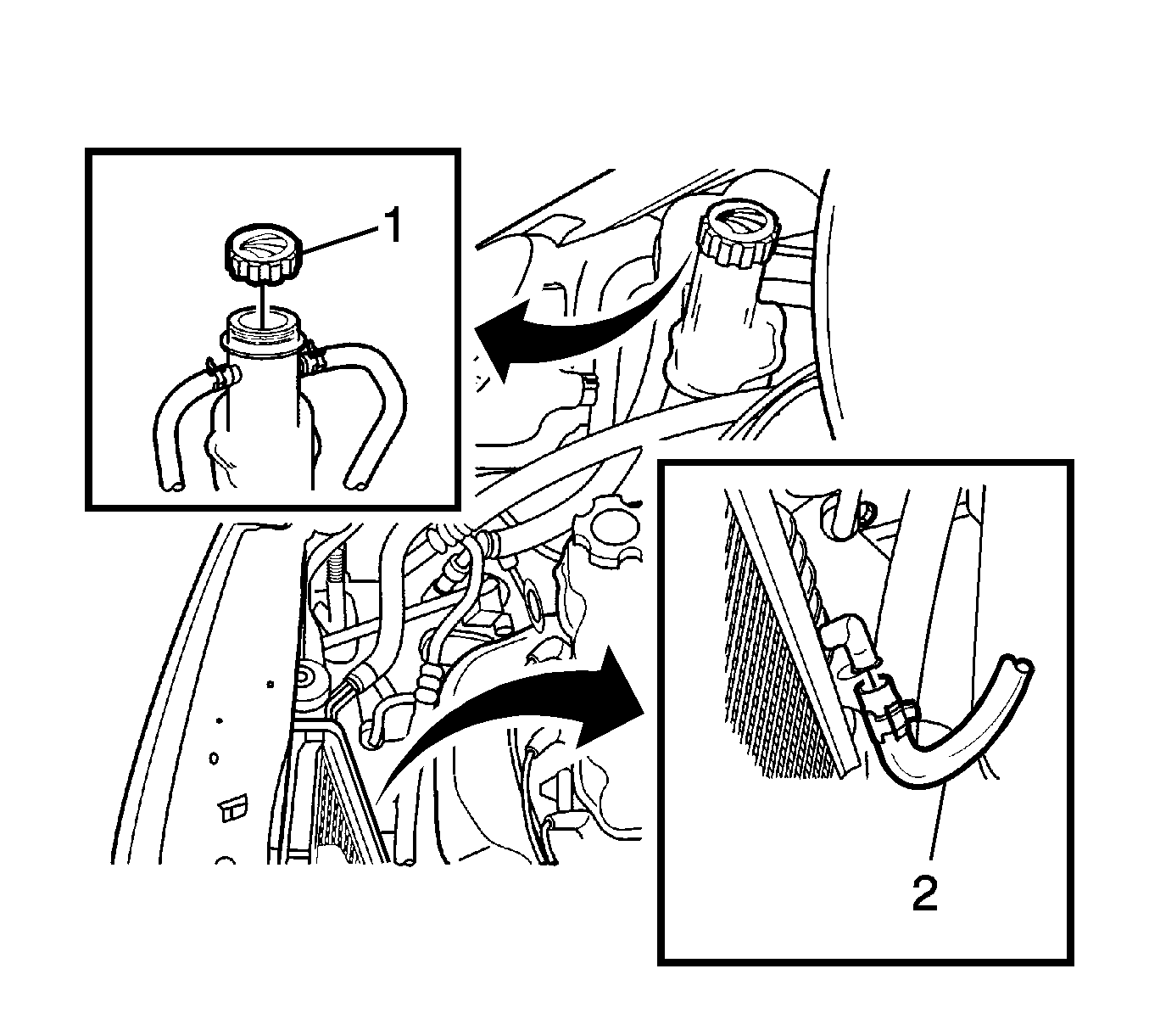
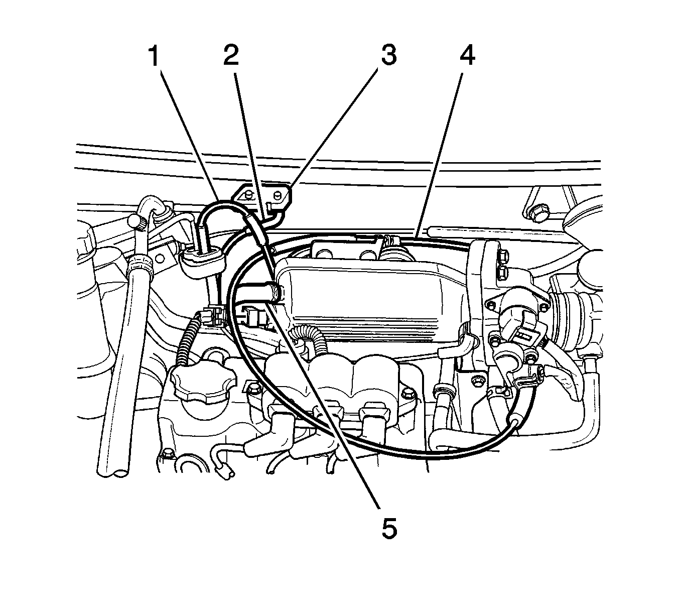
- Remove the surge tank cap (1).
- Disconnect the radiator lower hose and drain the coolant (2). Refer to Cooling System Draining and Filling.
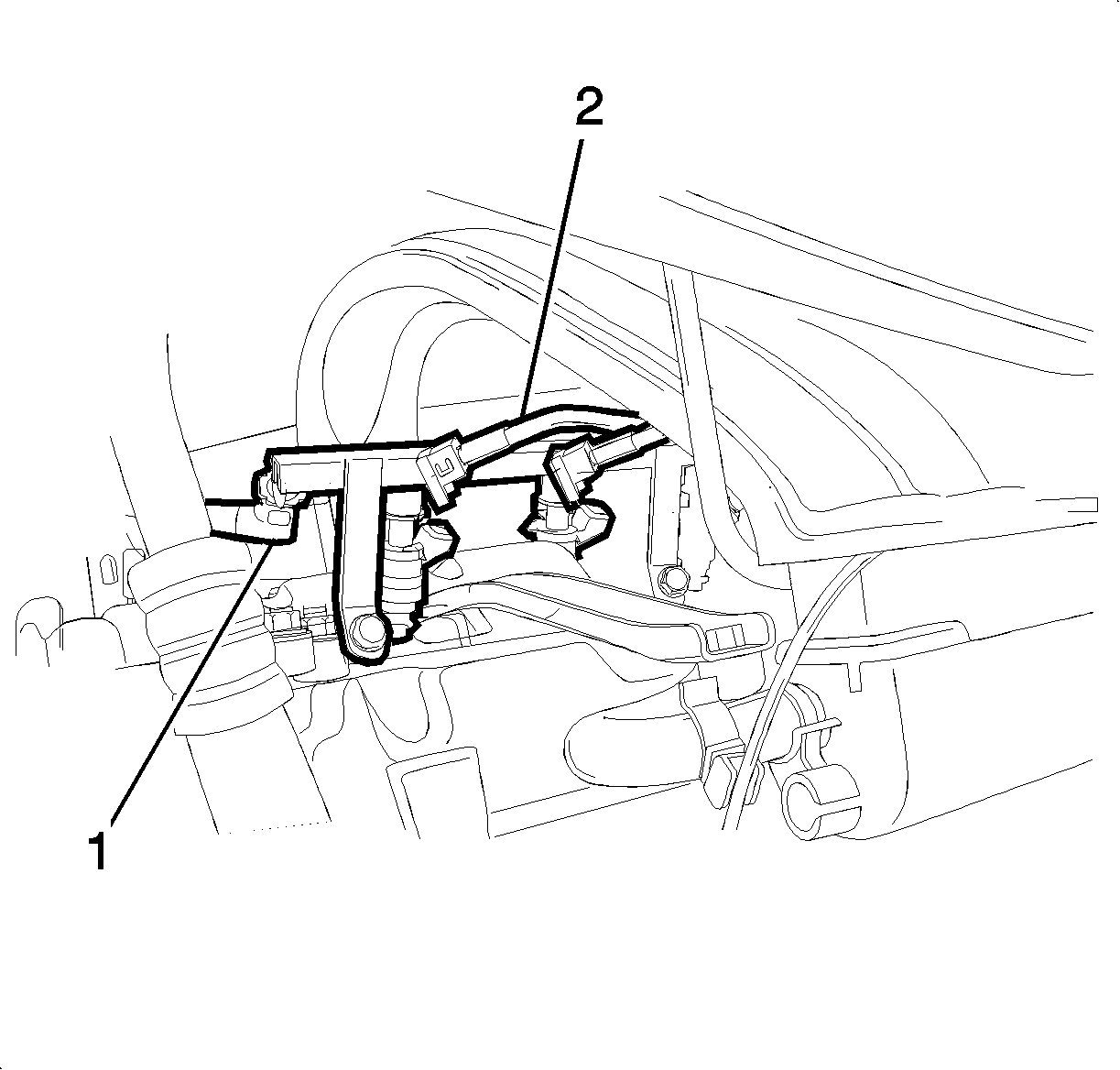
- Disconnect the fuel injector wire connectors and fuel line inlet hose. (2)
- Disconnect the throttle cable (4).
- Disconnect the manifold absolute pressure (MAP) sensor connector (3).
- Disconnect the canister solenoid connector (1).
- Disconnect the brake booster vacuum hose (5).
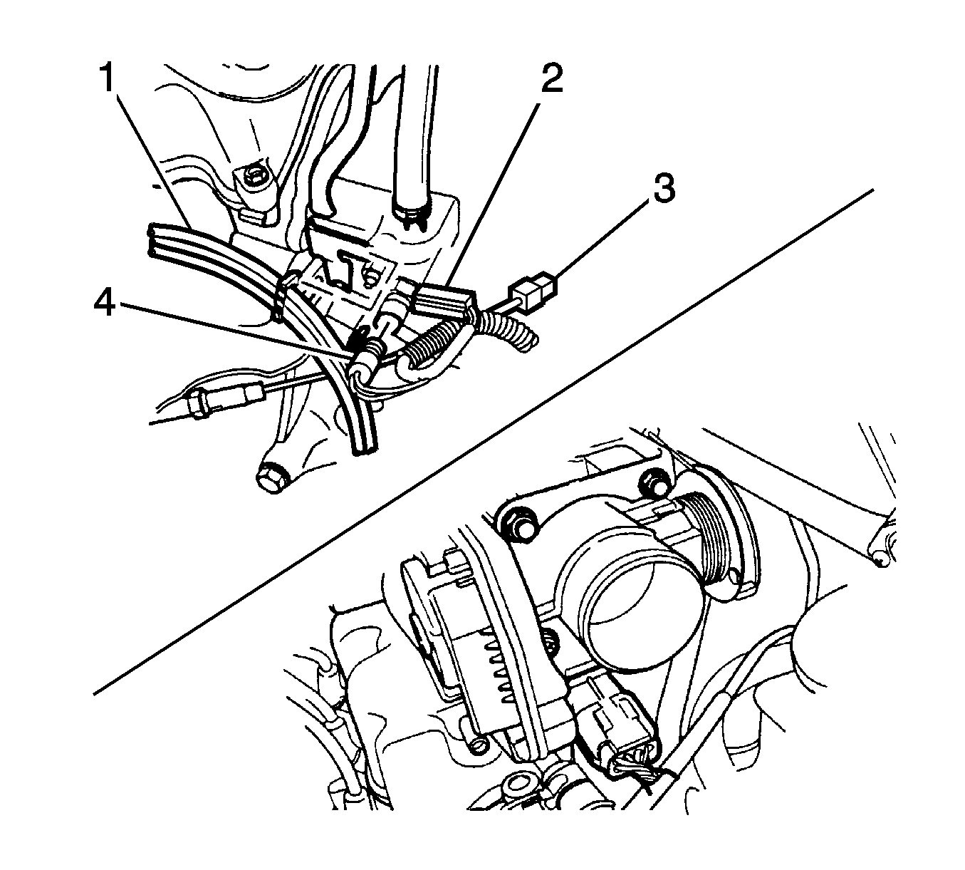
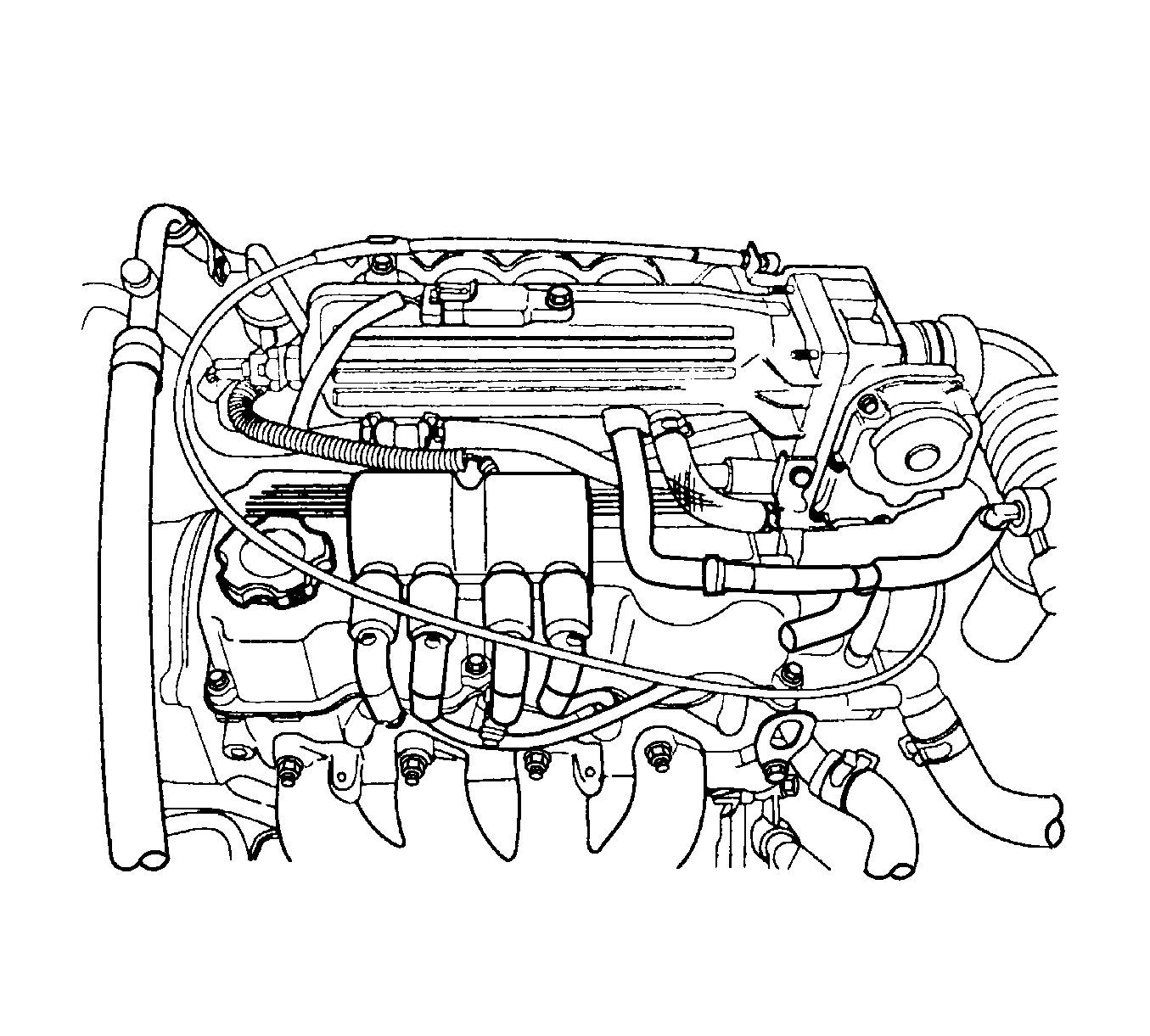
- Disconnect the ignition wires (1) from the spark plugs.
- Disconnect the engine coolant temperature sensor connector (2).
- Disconnect the coolant temperature sensor connector (4).
- Disconnect the oxygen sensor connector (3).
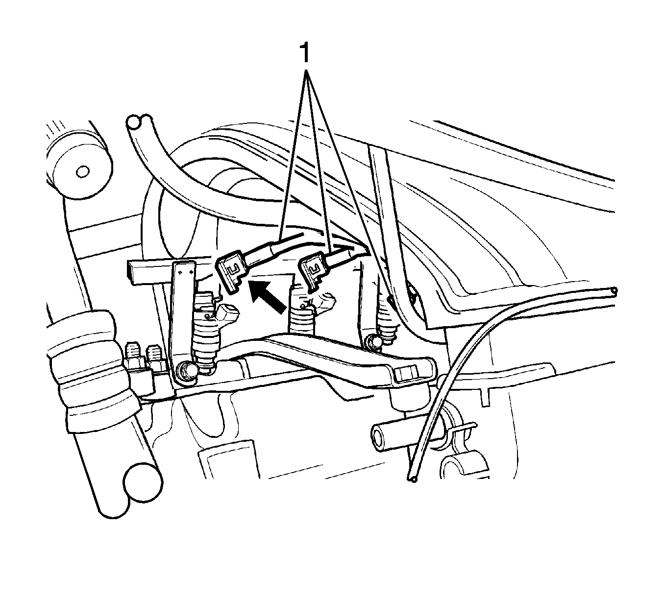
- Disconnect the fuel injector wire connector (1).
- Disconnect the distributor optical sensor connector.
- Remove the exhaust gas recirculation (EGR) solenoid.
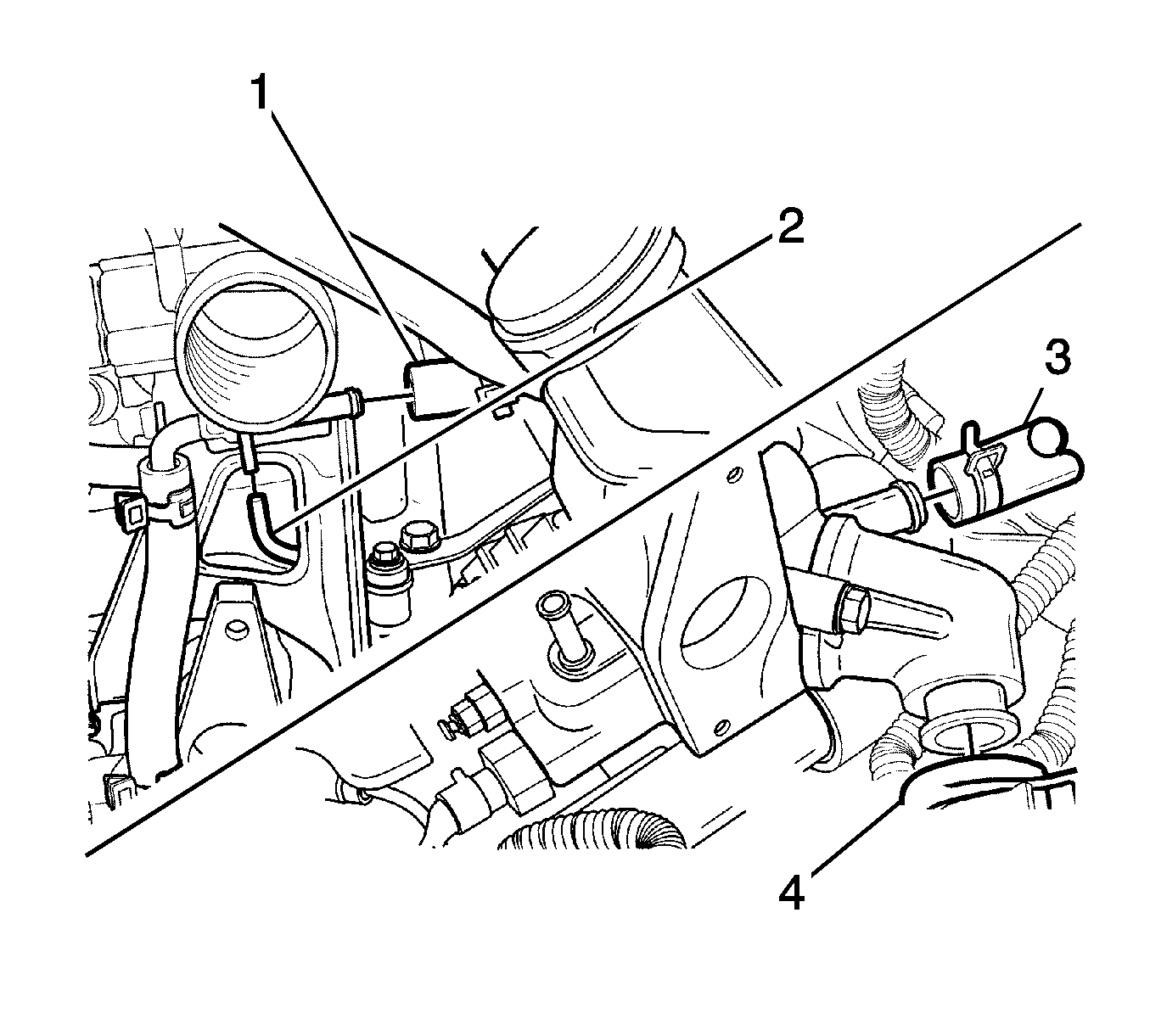
- Disconnect the evaporative emission canister vacuum tube (2).
- Disconnect the radiator upper hose from the thermostat housing (3).
- Disconnect the heat core inlet hose from the thermostat housing (4).
- Remove the timing belt. Refer to Timing Belt Replacement.
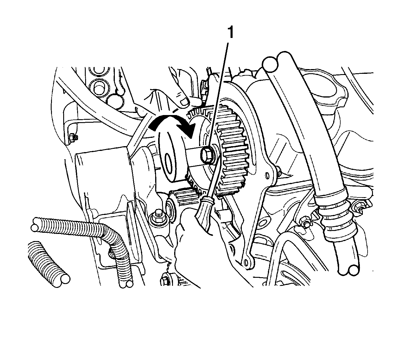
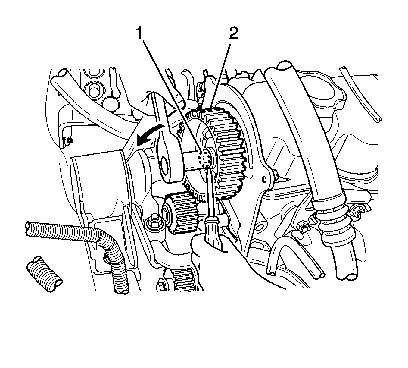
- Remove the camshaft gear bolt (1).
- Remove the camshaft gear from the camshaft (2).
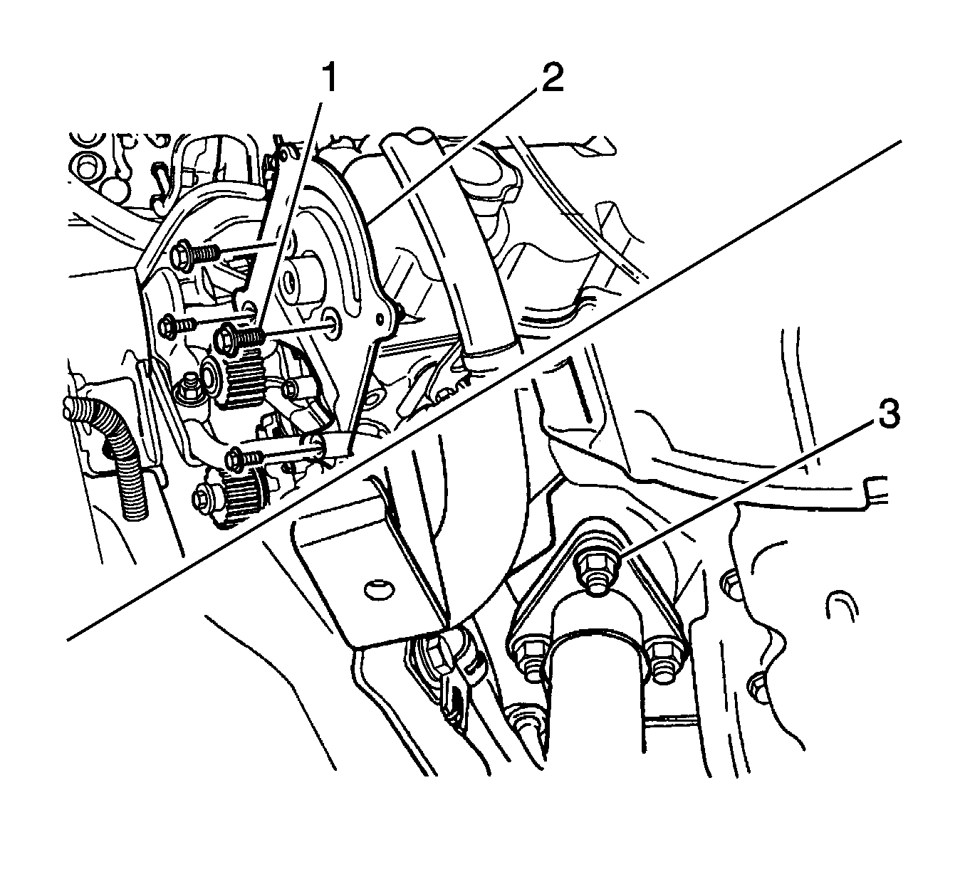
- Remove the timing belt rear cover bolts (1).
- Remove the rear cover from the cylinder head and block (2).
- Remove front exhaust pipe nuts and gasket.
- Remove front exhaust pipe.
- Disconnect the MAP sensor vacuum tube.
- Disconnect the positive crankcase ventilation (PCV) hose and valve.
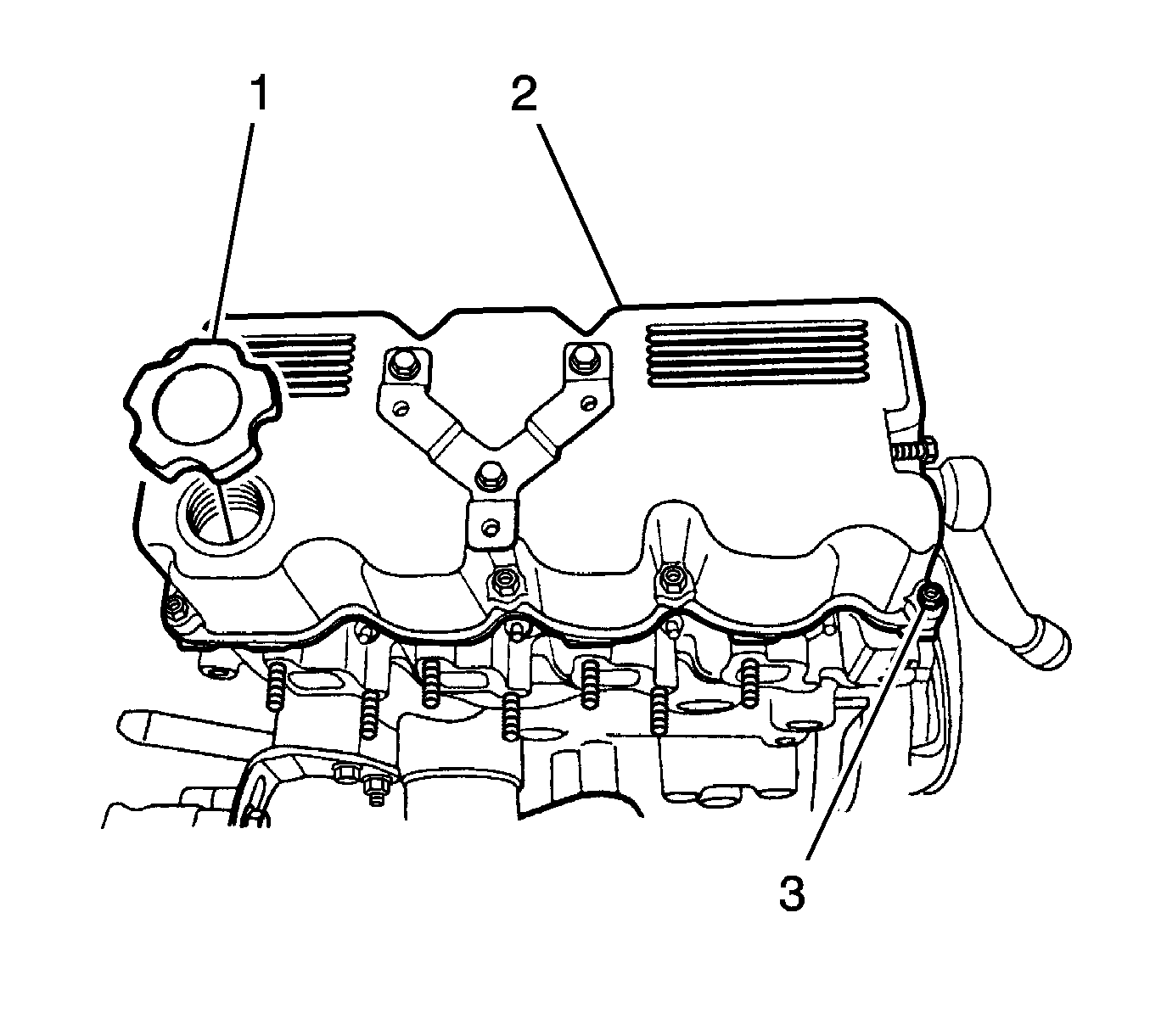
- Remove the oil filter cap.
- Remove the ignition coil.
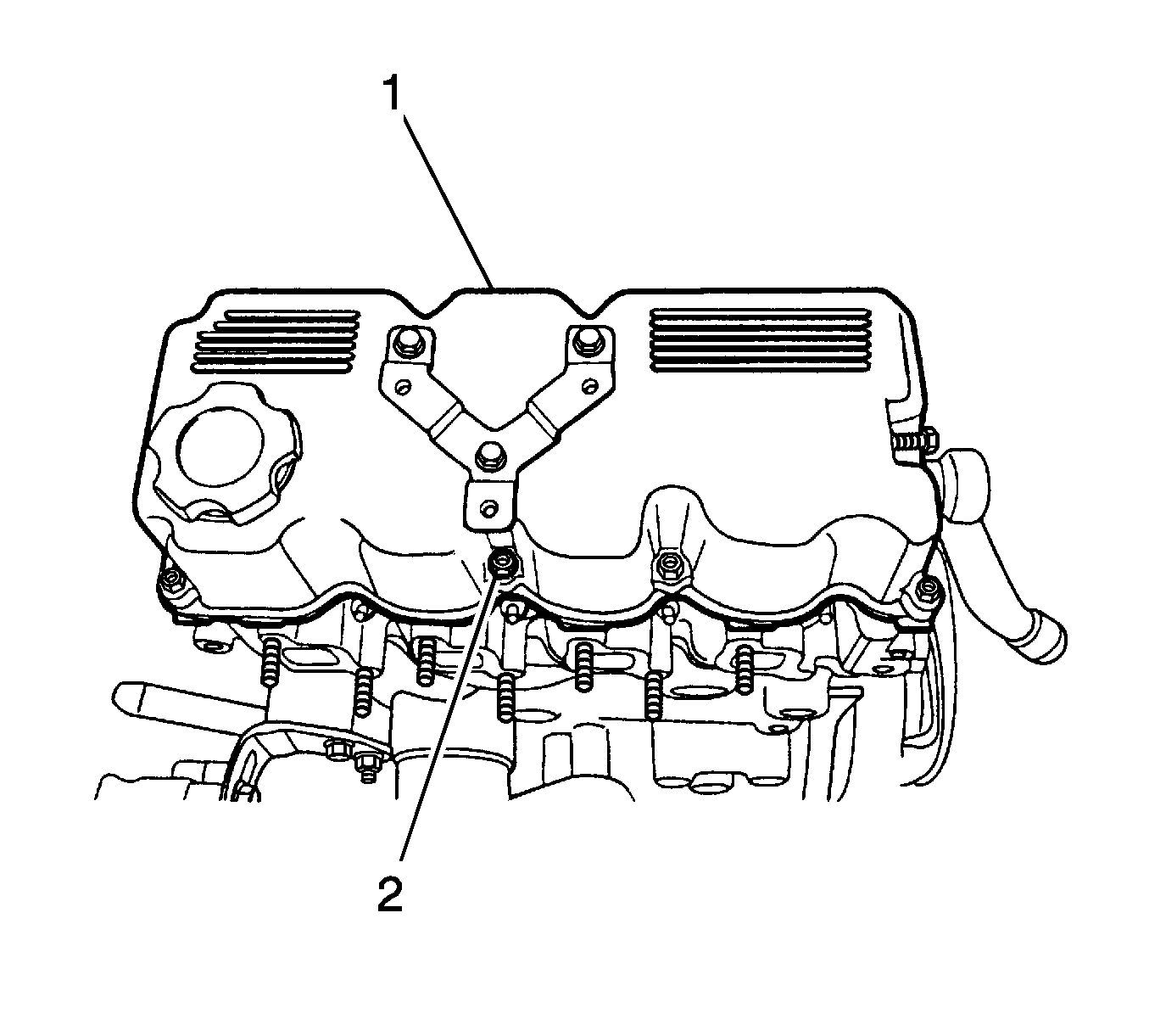
- Remove the cylinder head cover hexagon bolts (2).
- Remove the cylinder head cover with gasket (1).
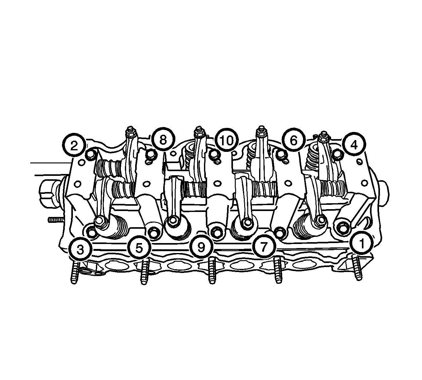
- Gradually loosen all of the cylinder head bolts in the sequence shown.
- Remove the cylinder head bolts (1).
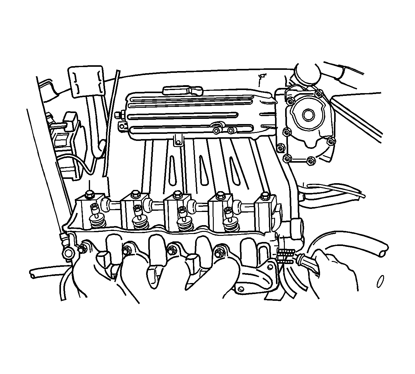
- Remove the cylinder head assembly from the engine block, with the intake/exhaust manifold, throttle body, distributor housing cylinder head gasket (2).
- Inspect the cylinder head for damage.
- Clean the gasket surfaces of the cylinder head and engine block.
- Clean the cylinder head bolts.
Warning: Refer to Safety Glasses Warning in the Preface section.
Warning: Remove the fuel tank cap and relieve the fuel system pressure before servicing the fuel system in order to reduce the risk of personal injury. After you relieve the fuel system pressure, a small amount of fuel may be released when servicing the fuel lines, the fuel injection pump, or the connections. In order to reduce the risk of personal injury, cover the fuel system components with a shop towel before disconnection. This will catch any fuel that may leak out. Place the towel in an approved container when the disconnection is complete.
Warning: Refer to Battery Disconnect Warning in the Preface section.
Installation Procedure
- Install new cylinder head gasket.
- Install the cylinder head bolts in the sequence shown and tighten to 65-70 N·m (48-52 lb ft).
- Install cylinder head assembly to engine block.
- Install the cylinder head hexagon bolts (3) and tighten to 9-12 N·m (80-106 lb in).
- Install the ignition coil.
- Install the oil filter and cap.
- Connect the PCV hose and valve.
- Install front exhaust pipe, gasket, and nuts (3) and tighten to 25-35 N·m (18-25 lb ft).
- Install timing belt rear cover to the cylinder head and block bolts (1) and tighten to 9-12 N·m (80-106 lb in).
- Install the camshaft gear to the camshaft with bolts (1) and tighten to 50-60 N·m (36-44 lb ft).
- Install the timing belt. Refer to Timing Belt Replacement.
- Connect the heat core inlet hose to the thermostat housing (4).
- Connect the radiator upper hose to the thermostat housing (3).
- Connect the evaporative emission canister vacuum tube (2).
- Install the EGR solenoid.
- Connect the distributor optical sensor connector.
- Connect the fuel injector wire connector (1).
- Connect the oxygen sensor connector (3).
- Connect the coolant temperature sensor connector (4).
- Connect the engine coolant temperature sensor connector (2).
- Connect the ignition wires to the spark plugs.
- Connect the brake booster vacuum hose (5).
- Connect the canister solenoid connector (1).
- Connect the MAP sensor connector (3).
- Connect the throttle cable (4).
- Connect the fuel line inlet hose (2) and the fuel injector wire connector (1).
- Connect radiator lower hose (2) and fill coolant. Refer to Cooling System Draining and Filling.
- Install the surge tank cap (1).
- Install the snorkel assembly, resonator and air filter. Refer to Air Cleaner Assembly Replacement.
- Connect the negative battery cable.

Caution: Refer to Fastener Caution in the Preface section.
