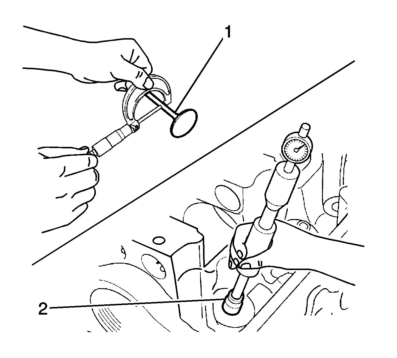
- Measure the outer diameter of the valve stem using a micrometer (1).
- Measure the inner diameter of the valve guide using a bore gage, at least 1 place in the direction to valve length (2).
- Measure the clearance between the valve stem and the valve guide.
Specifications
| • | The valve stem outer diameter standard (in) is 5.465-5.480 mm (0.2152-0.2157 in). |
| • | The valve stem outer diameter standard (ex) is 5.440-5.455 mm (0.2142-0.2148 in). |
| • | The valve guide inner diameter standard (in) is 5.500-5.512 mm (0.2165-0.2170 in). |
| • | The valve guide inner diameter limit (in) is 5.53 mm (0.2177 in). |
| • | The valve guide inner diameter standard (ex) is 5.500-5.512 mm (0.2165-0.2170 in). |
| • | The valve guide inner diameter limit (ex) is 5.53 mm (0.2177 in). |
| • | The clearance between stem and guide standard (in) is 0.020-0.047 mm (0.0008-0.0019 in). |
| • | The clearance between stem and guide limit (in) is 0.07 mm (0.0028 in). |
| • | The clearance between stem and guide standard (ex) is 0.045-0.072 mm (0.0018-0.0028 in). |
| • | The clearance between stem and guide limit (ex) is 0.09 mm (0.0035 in). |
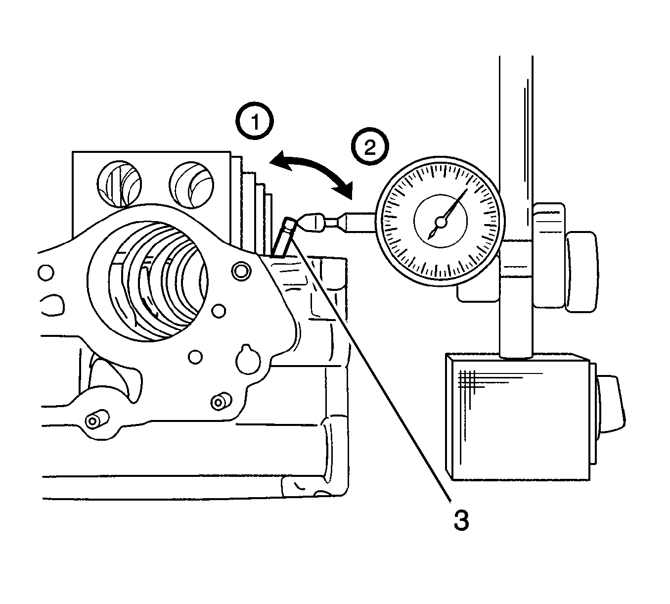
- If a bore gage is not available, measure the clearance using a dial gage by moving the edge of the stem to the directions of (1, 2, 3).
- Replace the valve stem or valve guide, if the measured valve is over the limit.
Specifications
| • | The edge of the valve clearance limit (in) is 0.14 mm (0.0055 in). |
| • | The edge of the valve clearance limit (ex) is 0.18 mm (0.0071 in). |
Valve
- Remove all carbon from the valve.
- Check the valve or stem for abrasion, burn or bending, and replace as necessary.
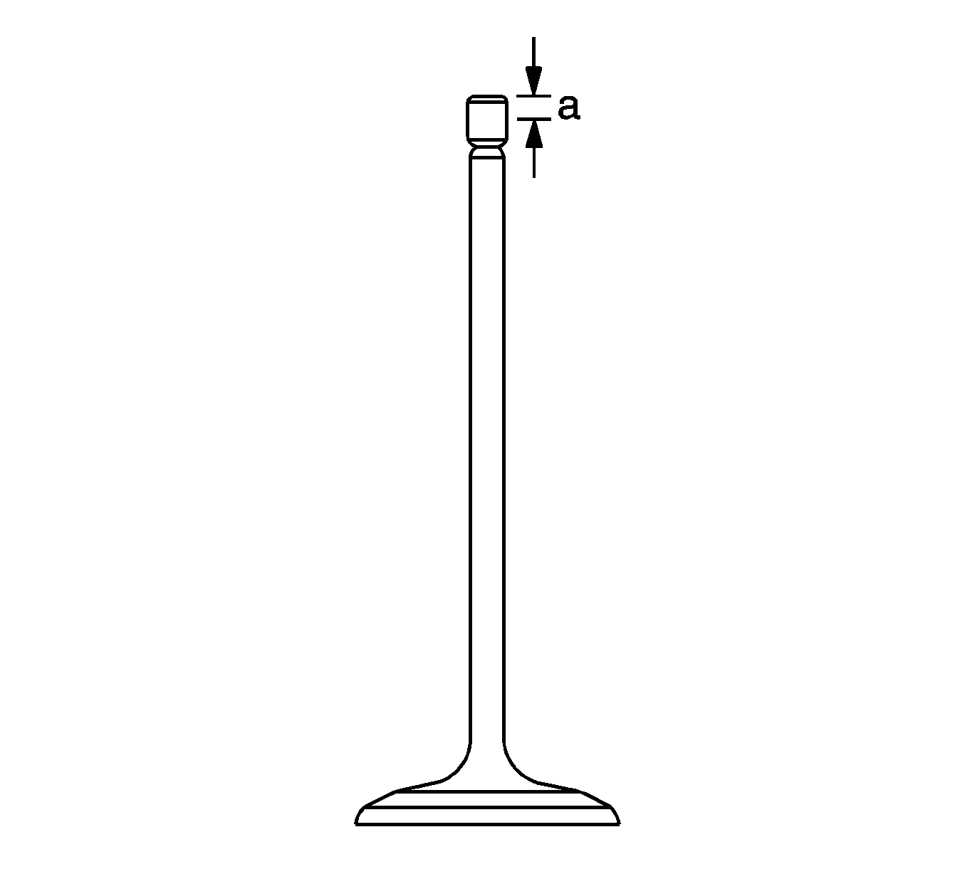
- Check the edge of each valve for abrasion. Some uneven abrasion would be made on the edge because the rocker arm gets contacted at this surface when operating. Repair the section within 0.05 mm (0.002 in) as required, or replace the
valve if some modification is required more than that (1).
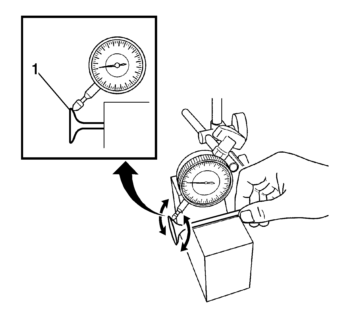
- Measure the deviation to the rotating direction using a dial gage and the V block by turning the valve slowly.
- Replace valve, if the measured value exceeds the limit.
Specifications
The deviation limit of valve head to the rotating direction is 0.08 mm (0.0031 in).
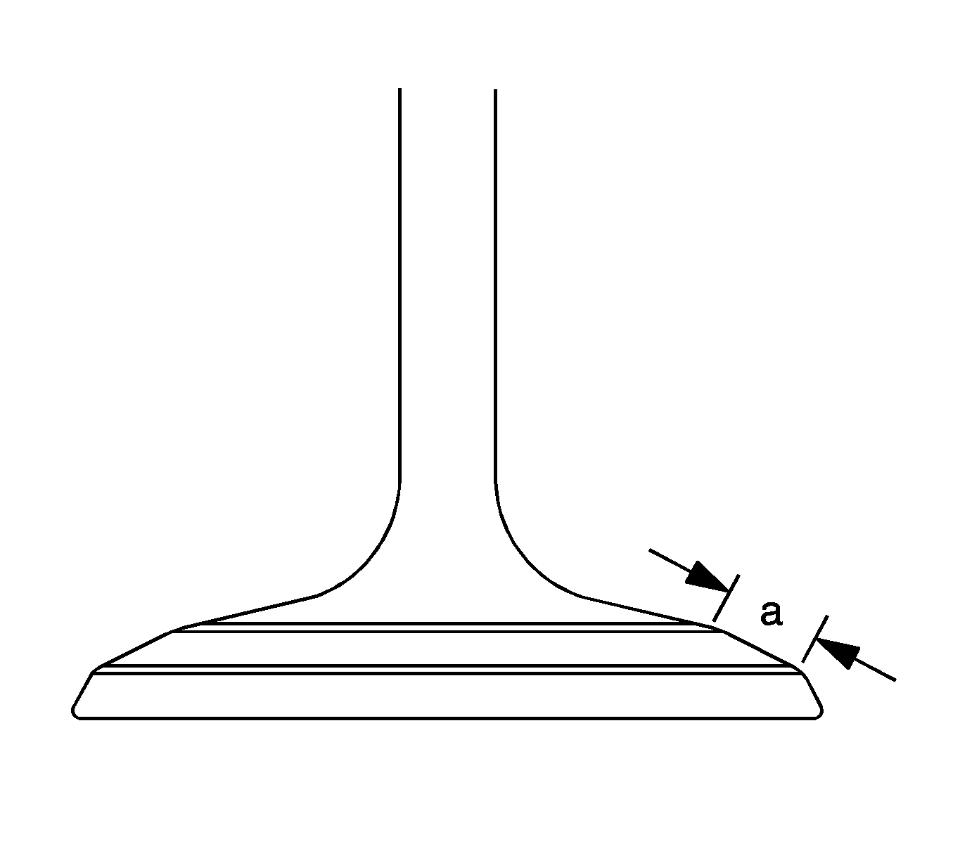
- Inspect the contact width (3).
Warning: Refer to Safety Glasses Warning in the Preface section.
- Clean the valve and the valve seat and apply red stamping ink thinly to the contacting surface of the valve seat. Check the fitness after installing the valve unit.
- A good contact shows the equal contact width within the specified.
Specifications
| • | The contact width on the surface of the valve seat limit (in) is 1.46-1.66 mm (0.0575-0.0654 in). |
| • | The contact width on the surface of the valve seat limit (ex) is 1.46-1.66 mm (0.0575-0.0654 in). |
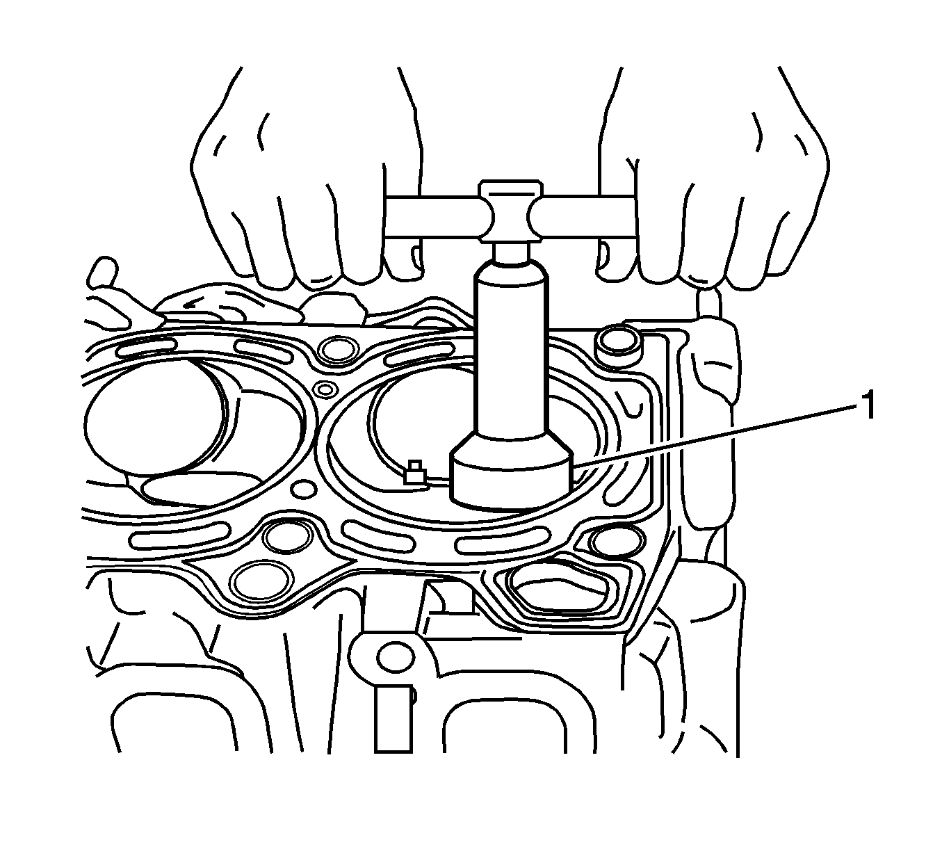
Note: Upon cutting, take care of the contact width. Finish the cutting with gradually reduced power for no cutting mark on the surface.
- Repair by grinding and cutting off the valve seat, and lap it if its contacting width is not even or out of the specified.
- Upon applying a seat cutter, use the one of smaller angle first and increase the angle of the using cutter up to the light and final modification of the contact. Finish the contact surface and its location with the cutter of 45 degrees.
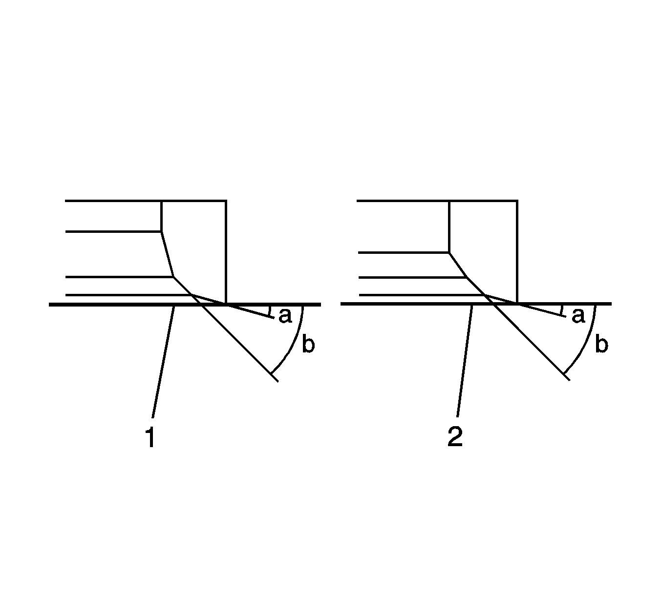
- Make valve lapping in 2 stages, first with normal lap and second with fine one for both the intake side (1) and the exhaust side (2).


