GM Service Manual Online
For 1990-2009 cars only

Antilock Brake System (ABS) Components

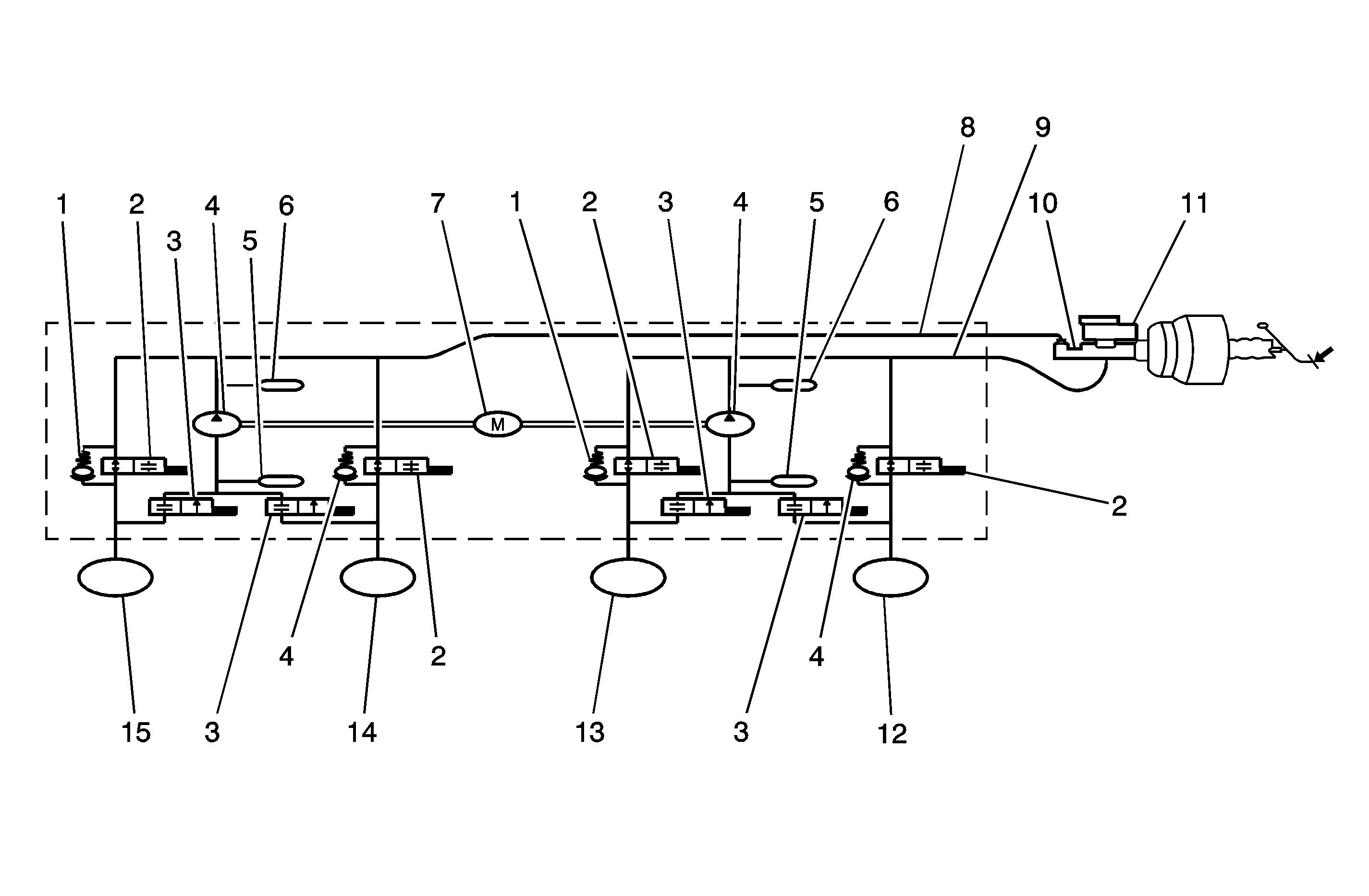
The ABS 5.3 antilock braking system (ABS) consists of a conventional hydraulic brake system plus antilock components. The conventional brake system includes a vacuum booster, master cylinder, front disc brakes, rear leading/trailing drum brakes, interconnecting hydraulic brake pipes and hoses, brake fluid level sensor and the BRAKE indicator.

The ABS components include a hydraulic unit, an electronic brake control module (EBCM), 2 system fuses, 4 wheel speed sensors, one at each wheel, interconnecting wiring, the ABS indicator, the EBD indicator, which is connected to the parking lamp, and the rear disk brakes.

The hydraulic unit with the attached EBCM is located near the coolant recovery reservoir on the left side of the vehicle.

The basic hydraulic unit configuration consists of hydraulic check valves, 2 solenoid valves for each wheel, a hydraulic pump, 2 accumulators, and 2 dampers. The hydraulic unit controls hydraulic pressure to the front calipers and rear wheel cylinders to prevent wheel lockup.

Nothing in the hydraulic unit or the EBCM is serviceable. In the event of any failure, the entire ABS unit with the attached EBCM must be replaced.

Base Braking Mode


Object Number: 1291783  Size: MF
(1)Check Valve
(2)Inlet Valve
(3)Outlet Valve
(4)Pump
(5)Accumulator
(6)Damper
(7)Pump Motor
(8)Hydraulic Circuit 2
(9)Hydraulic Circuit 1
(10)Master Cylinder
(11)Master Cylinder Reservoir
(12)Right Rear
(13)Left Front
(14)Right Front
(15)Left Rear

The baseline braking mode of the ABS 5.3 system used in this vehicle is a diagonal split system. In this system, one master cylinder circuit supplies pressure to the right front and the left rear brakes; the other circuit supplies pressure to the left front and the right rear brakes. All valves in the hydraulic modulator are in their normal, non-energized positions.

Antilock Braking Mode-Apply


Object Number: 1291792  Size: MF
(1)Left Rear
(2)Right Front
(3)Left Front
(4)Right Rear

If a wheel speed sensor detects a wheel locking up, the electronic brake control module (EBCM) closes the normally open inlet valve for the brake on that wheel to prevent adding more hydraulic pressure to that brake.

Antilock Braking Mode-Hold


Object Number: 1291793  Size: MF
(1)Left Rear
(2)Right Front
(3)Left Front
(4)Right Rear

If the information from the wheel speed sensors indicate excessive wheel deceleration (imminent lockup), the first step in the antilock sequence is to isolate the brake pressure being applied by the driver. The EBCM sends a voltage to the coil to energize and close the inlet valves by pulling down on the armature. This prevents any additional fluid pressure applied by the driver from reaching the wheel. Though each channel of the 4-channel system can operate independently, once any front channel (brake) sees excessive deceleration, both front inlet valves are energized and close thus, with the inlet valves closed, further unnecessary increases in the brake pressure will be prohibited.

Antilock Braking Mode-Release

If the wheel locking tendency continues, the EBCM releases the hydraulic pressure at that brake by opening the outlet valve for that wheel.
Electronic Brake Force Distribution (EBD) System


Object Number: 1290268  Size: SH
(1)Magnetic Permeability, Rear Axle = 0.8
(2)Ideal Braking Force Distribution
(3)Intervention ABS Front and Rear Axle
(4)Braking Force Front Axle
(5)Magnetic Permeability, Front Axle = 0.8
(6)Intervention ABS at Rear Axle
(7)Deceleration Z c = 0.4
(8)Intervention EBD
(9)Braking Force Rear Axle

As an add-on logic to the antilock brake system (ABS) base algorithm, electronic brake force distribution (EBD) works in a range in which the intervention thresholds for ABS control are not reached yet.

EBD ensures that the rear wheels are sensitively monitored for slip with respect to the front axle. If slip is detected, the inlet valves for the rear wheels are switched to pressure hold to prevent a further increase in pressure at the rear-wheel brakes, thus electronically reproducing a pressure-reduction function at the rear-wheel brakes.

The Benefits of Electronic Brake Force Distribution (EBD)

    • Elimination of the conventional proportioning valve
    •  EBD utilizes the existing rear axle wheel speed sensor to monitor rear wheel slip.
    • Based on many variables in algorithm, a pressure hold, increase and/or decrease pulse train may be triggered at the rear wheels insuring vehicle stability.
    • Vehicle approaches the ideal brake force distribution, front to rear
    •  Constant brake force distribution during vehicle lifetime
    • EBD function is monitored via ABS safety logic. Conventional proportioning valves unable to be monitored.
    • Keep alive function

Electronic Brake-Force Distribution (EBD) Failure Matrix


Object Number: 1290286  Size: LF

Tires and ABS/EBD

Replacement Tires

Tire size is important for proper performance of the antilock brake system (ABS). Replacement tires should be the same size, load range, and construction as the original tires. Replace tires in axle sets and only with tires of the same tire performance criteria (TPC) specification number. Use of any other size or type may seriously affect the ABS operation.

Important: There is no serviceable or removable electrically erasable programmable read only memory (EEPROM). The electronic brake control module (EBCM) must be replaced as an assembly.

The EBCM is attached to the hydraulic unit in the engine compartment. The controlling element of ABS 5.3 is a microprocessor-based EBCM. Inputs to the system include the 4 wheel speed sensors, the stop lamp switch, the ignition switch, and battery voltage. There is an output to a bi-directional serial data link, located in the data link connector (DLC) for service diagnostic tools and assembly plant testing.

The EBCM monitors the speed of each wheel. If any wheel begins to approach lockup and the brake switch is closed, brake pedal depressed, the EBCM controls the solenoids to reduce brake pressure to the wheel approaching lockup. Once the wheel regains traction, brake pressure is increased until the wheel again begins to approach lockup. This cycle repeats until either the vehicle comes to a stop, the brake pedal is released, or no wheels approach lockup.

Additionally, the EBCM monitors itself, each input, except the serial data link, and each output for proper operation. If it detects any system malfunction, the EBCM will store a DTC in nonvolatile memory (EEPROM). Diagnostic trouble codes (DTCs) will not disappear if the battery is disconnected.

Front Wheel Speed Sensor

The front wheel speed sensors are of a variable reluctance type. Each sensor is attached to the steering knuckle, close to a toothed ring. The result, as teeth pass by the sensor, is an alternating current (AC) voltage with a frequency proportional to the speed of the wheel. The magnitude of the voltage and frequency increase with increasing speed. The sensor is not repairable, nor is the air gap adjustable.

Front Wheel Speed Sensor Rings

The toothed ring mentioned above is pressed onto the wheel-side, outer, constant velocity joint. Each ring contains 40 equally spaced teeth. Exercise care during service procedures to avoid prying or contacting this ring. Excessive contact may cause damage to one or more teeth.

Rear Wheel Speed Sensor and Rings

The rear wheel speed sensors operate in the same manner as the front wheel speed sensors. Each sensor is attached to the backing plate, close to a toothed ring. They incorporate a length of flexible harness with the connector attached to the end of the harness. The rear wheel speed rings are incorporated into the hub drum.

Valve Relay and Pump Motor Relay

The valve relay and the motor pump relay are located inside the electronic brake control module (EBCM) and are not replaceable. If one should fail, replace the EBCM.

Wiring Harness

The wiring harness is the mechanism by which the electronic brake control module (EBCM) is electrically connected to power and to ground, to the wheel speed sensors, the fuses, the switches, the indicators, and the serial communications port. The components, considered part of the wiring harness, are the wires that provide electrical interconnection, and connectors, terminals, pins, contacts, or lugs, that provide an electrical/mechanical interface from the wire to a system component.

Indicators

The electronic brake control module (EBCM) continuously monitors itself and the other antilock brake system (ABS) components. If the EBCM detects a problem with the system, the amber ABS indicator will light continuously to alert the driver to the problem. An illuminated ABS indicator indicates that the ABS system has detected a problem that affects the operation of ABS. No antilock braking will be available. Normal, non-antilock brake performance will remain. In order to regain ABS braking ability, the ABS must be serviced.

Important: The electronic brake force distribution (EBD) indicator lamp wiring is connected to the parking brake indicator. If the parking brake indicator is turned ON when you are driving, check on whether the parking brake lever is engaged or the brake fluid level is low. If the system has no problem, the EBD system is working improperly. The EBD system must be serviced.

The red BRAKE indicator will be illuminated when the system detects a low brake fluid level in the master cylinder or when the parking brake switch is closed, the parking brake is engaged, or the EBD system is disabled.