Removal Procedure
- Disconnect the negative battery cable and let the vehicle sit for 1 minute to deactivate the air bag.
- Remove the lower instrument panels. Refer to Knee Bolster Replacement .
- Remove the upper and the lower steering column cover panels by removing the screws.
- Remove the switch levers. Refer to Turn Signal Multifunction Switch Replacement and Windshield Wiper and Washer Switch Replacement .
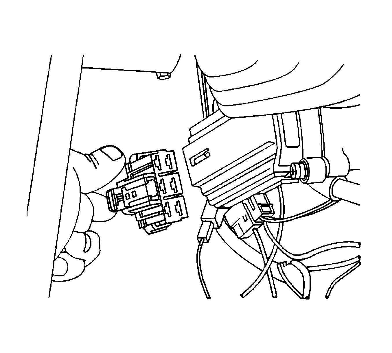
- Remove the immobilizer module. Refer to Theft Deterrent Module Replacement .
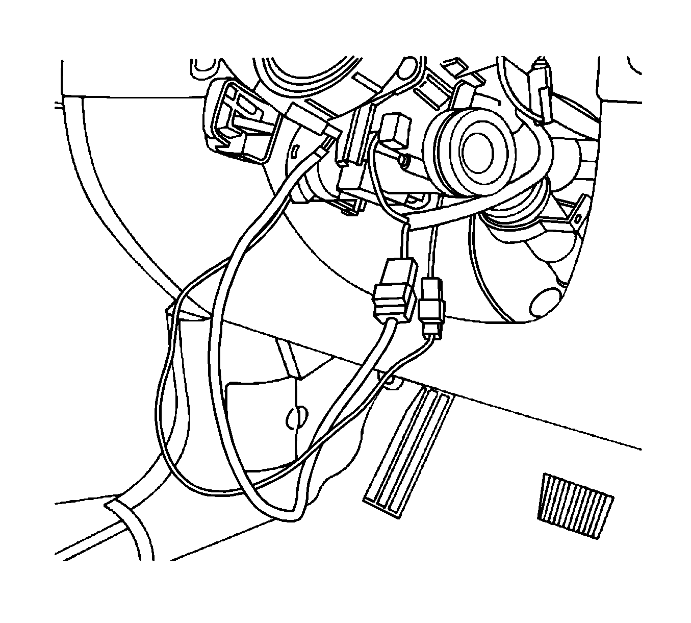
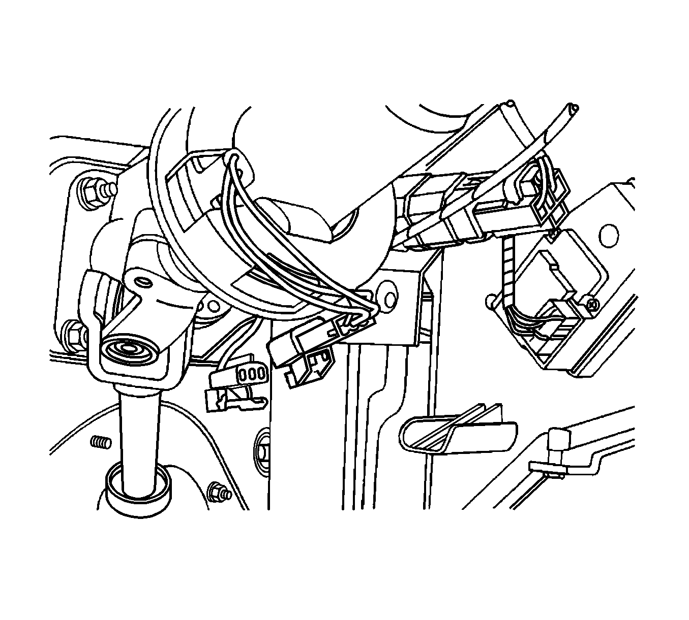
- Disconnect the air bag electrical connections.
- Disconnect the ignition switch electrical connection.
- Adjust the steering to the straight-ahead position.
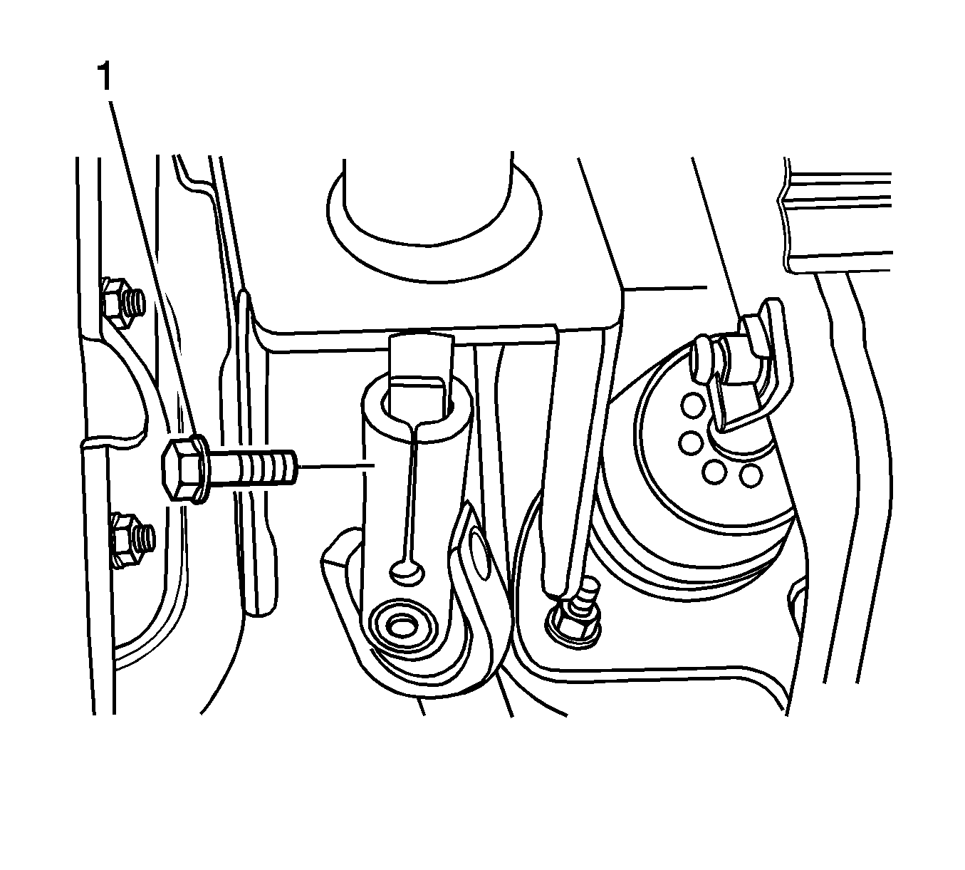
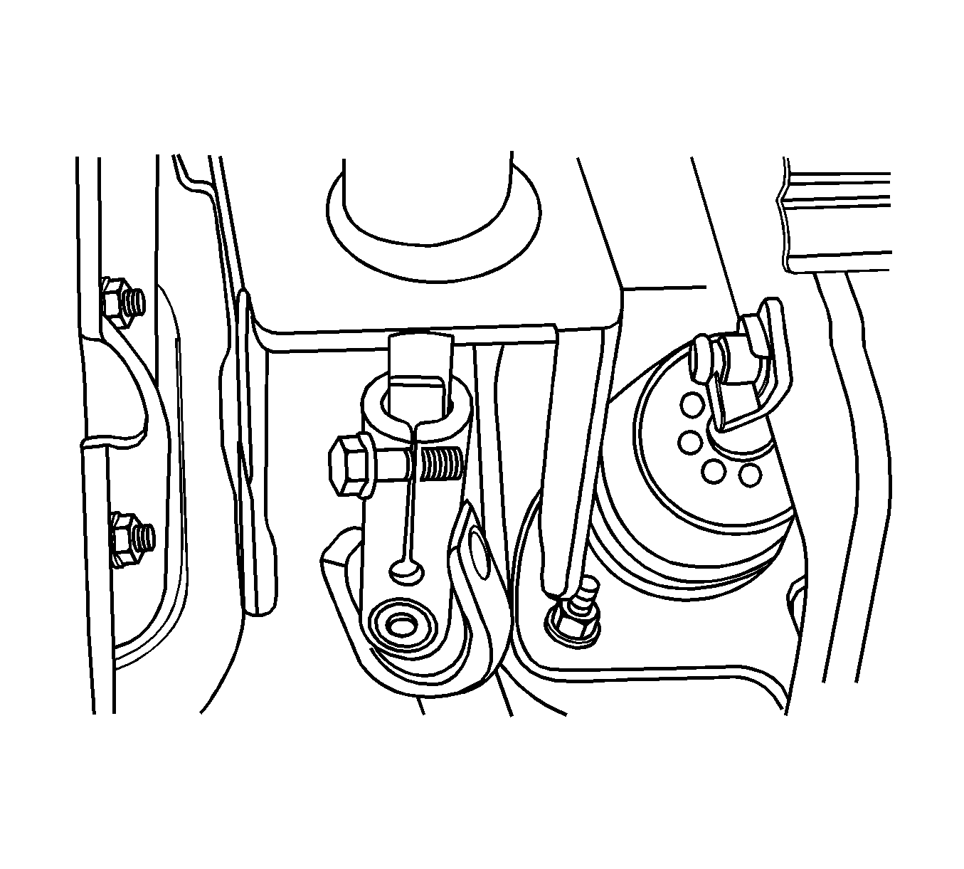
- Remove the pinch bolt from the intermediate shaft universal joint.
- Disconnect the speed sensitive steering electrical connector.
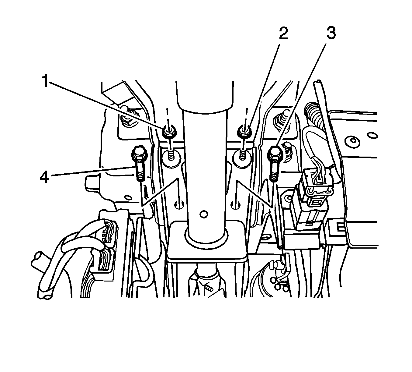
- Remove the bolts and nuts holding the front bracket of the steering column jacket assembly.
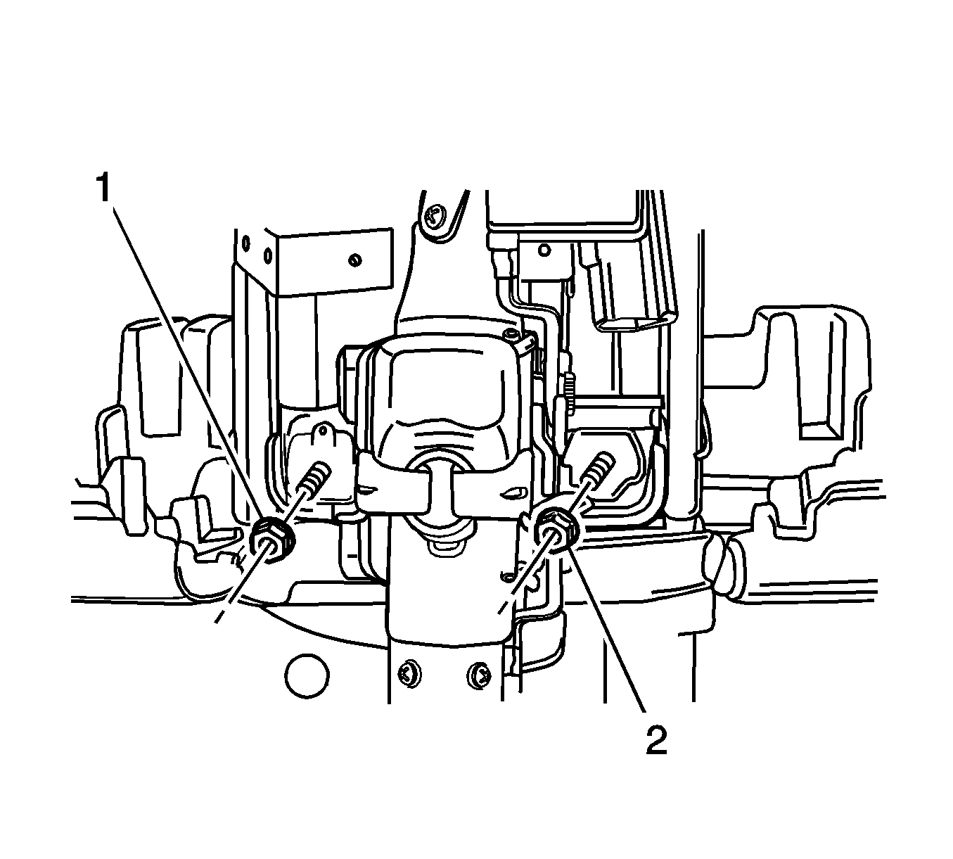
- Remove the nuts holding the rear bracket of the steering column jacket assembly.
- Guide the steering column assembly out of steering shaft flange and carefully lay down the assembly.
Caution: Refer to Battery Disconnect Caution in the Preface section.
Notice: Once the steering column is removed from the vehicle, the column is extremely susceptible to damage. Dropping the column assembly on the end could collapse the steering shaft or loosen the plastic injections, which maintain column rigidity. Leaning on the column assembly could cause the jacket to bend or deform. Any of the above damage could impair the columns collapsible design. Do NOT hammer on the end of the shaft, because hammering could loosen the plastic injections, which maintain column rigidity. If you need to remove the steering wheel, refer to the Steering Wheel Replacement procedure in this section.
Important: Remove the steering column only if the following conditions exist:
• The steering column requires replacement. • The steering and the ignition lock housing require replacement. • Another operation requires the removal of the steering column.
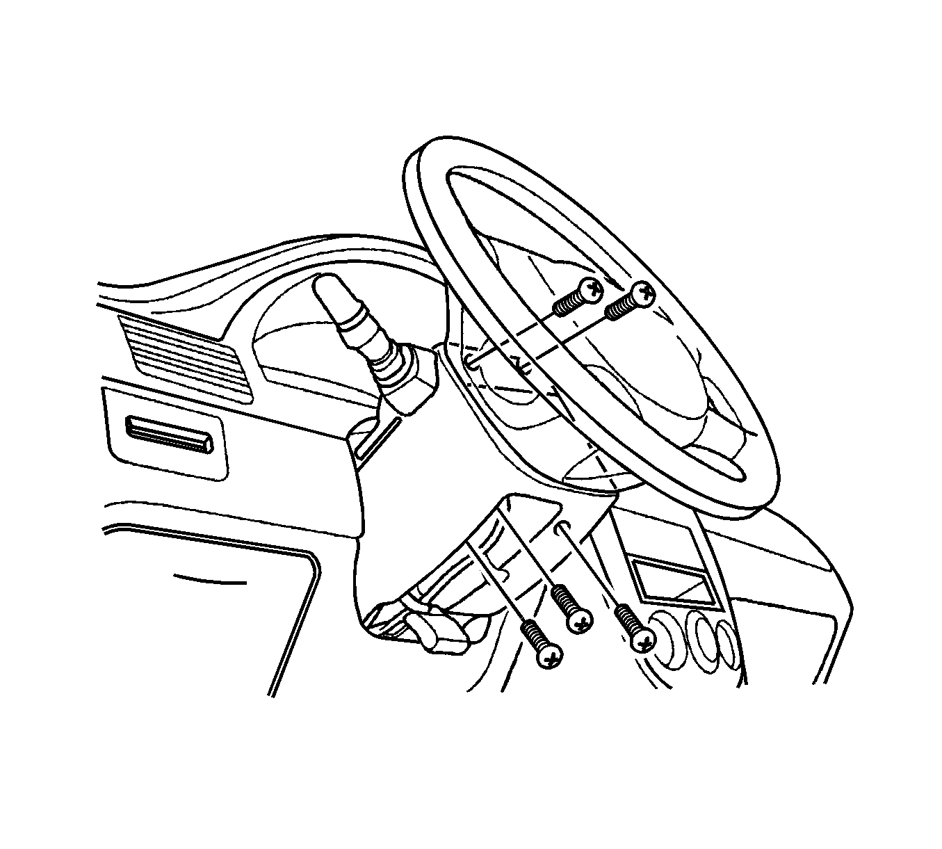
Important: The left-hand drive is shown. The right-hand drive is similar.
Installation Procedure
- Carefully guide the steering shaft into the intermediate shaft universal joint.
- Install the pinch bolt into the non-threaded hole of the flange.
- Install the bolts and nuts for the front bracket of the steering column jacket assembly.
- Install the nuts for the rear bracket of the steering column jacket assembly.
- Connect the speed sensitive steering electrical connector.
- Connect the ignition switch electrical connection.
- Connect the air bag electrical connections.
- Install the switch levers. Refer to Turn Signal Multifunction Switch Replacement and Windshield Wiper and Washer Switch Replacement .
- Install the immobilizer module. Refer to Theft Deterrent Module Replacement .
- Install the lower instrument trim panels. Refer to Knee Bolster Replacement .
- Install the upper and the lower steering column cover panel with the screws.
- Inspect the steering wheel in a straight-ahead position. Refer to Straight Ahead Inspection .
- Connect the negative battery cable.
Important: For proper installation of the steering column, be sure the steering wheel and the front wheels are in the straight-ahead position.
Notice: Refer to Fastener Notice in the Preface section.
Important: Provide support for the steering column assembly until the mounting nuts are fastened. Do not let the steering column assembly hang unsupported.
Tighten
Tighten the steering shaft universal joint pinch bolt to 25 N·m (18 lb ft).
Tighten
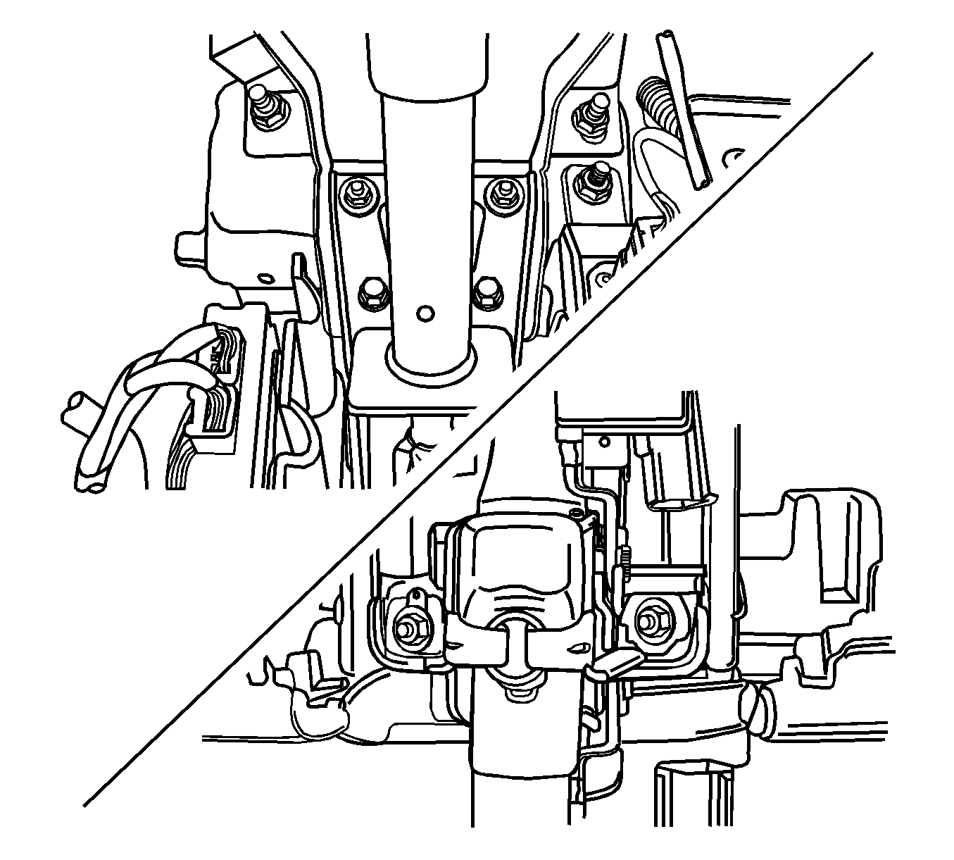
Tighten the steering column jacket assembly front bracket bolts to 22 N·m (16 lb ft).
Tighten
Tighten the steering column jacket assembly rear bracket nuts to 22 N·m (16 lb ft).


Tighten
Tighten the upper and the lower steering column panel screws to 2.5 N·m (22 lb in).
