Tools Required
| • |
| • |
| • |
| • |
| • |
| • |
| • |
| • |
| • |
| • |
Disassembly Procedure
- Remove the transaxle assembly from the vehicle. Refer to Transmission Replacement .
- Install the transaxle assembly to the transaxle support stand using theDT 46469-2 (1).
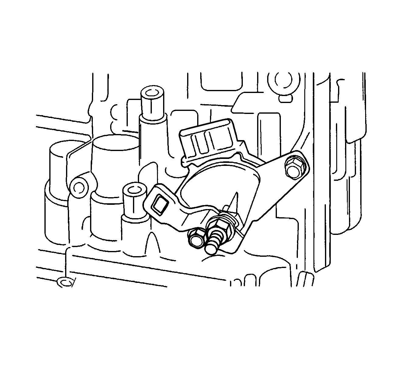
- Remove the nut, washer and control lever.
- Using a screwdriver, unstake the lock washer.
- Remove the 2 bolts and nut and pull out the park/neutral position (PNP) switch.
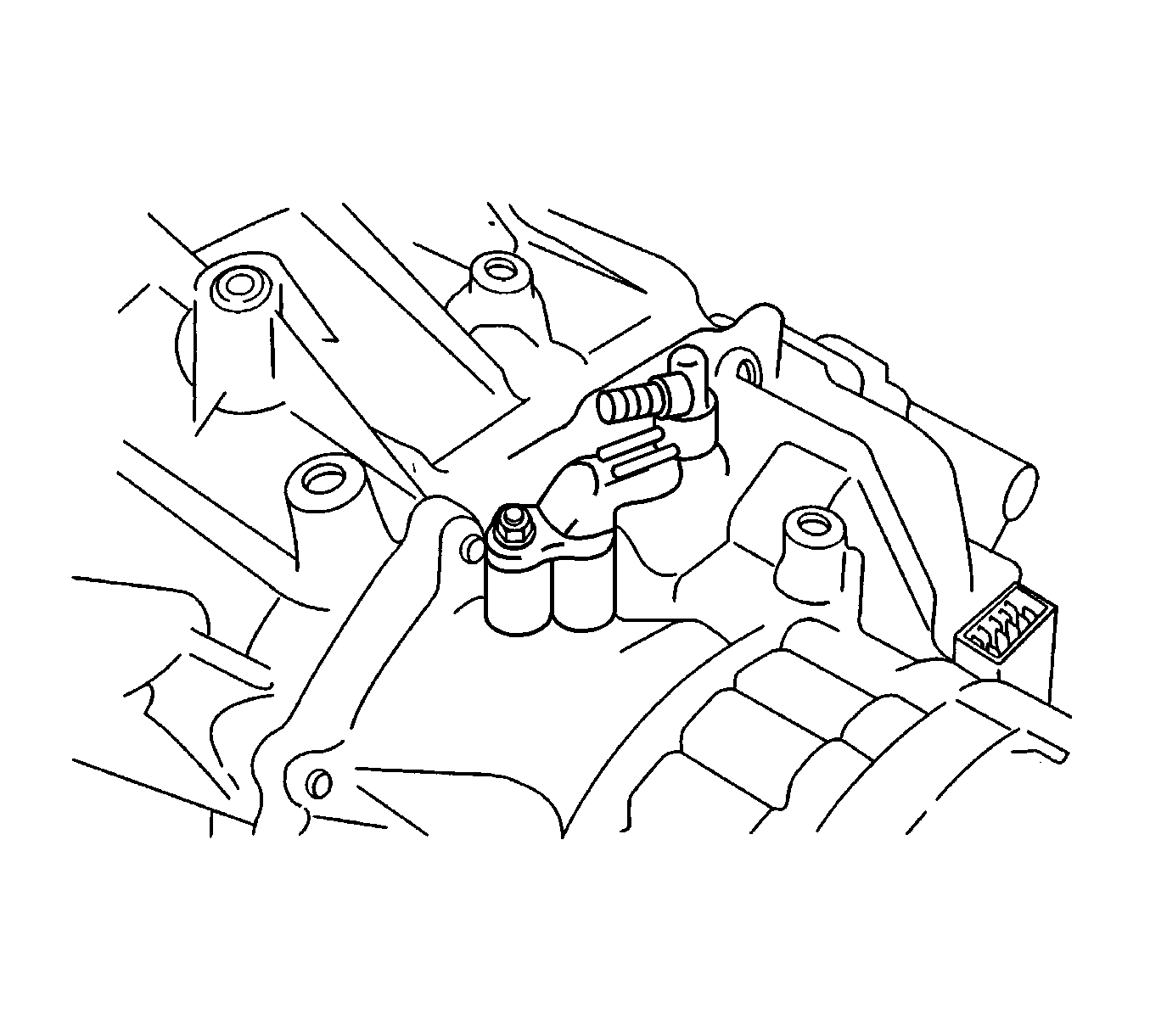
- Remove the 2 unions the transaxle case.
- Remove the 2 O-rings from the unions.
- Remove the screw plug from the transaxle case.
- Remove the O-ring from the screw plug.
- Remove the bolt and the input shaft speed (ISS) sensor.
- Remove the breather plug.
- Remove the O-ring from the breather plug.
- Remove the bolt and the output shaft speed (OSS) sensor.
- Remove the 18 bolts.
- Remove the oil pan and gasket.
- Remove the drain plug from the oil pan.
- Remove the 3 bolts and oil strainer.
- Remove the gasket from the oil strainer.
- Remove the bolt and transmission fluid temperature sensor with the clamp.
- Disconnect the 5 solenoid connectors.
- Support the valve body assembly and remove the 14 bolts.
- Disconnect the manual valve control rod from the manual valve lever, then remove the valve body assembly.
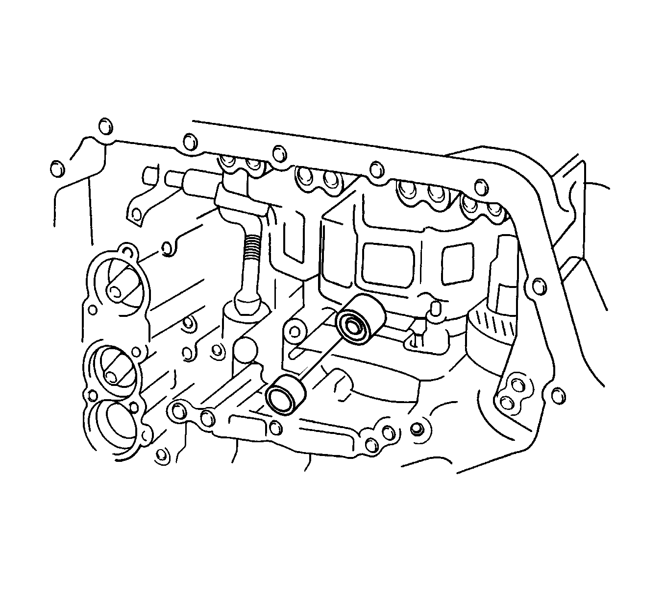
- Remove the check valve and spring.
- Remove the brake drum gasket.
- Remove the apply gasket.
- Apply 392 kPa (57 psi) of compressed air to the oil hole (1) and remove the direct clutch accumulator piston and spring.
- Remove the spring.
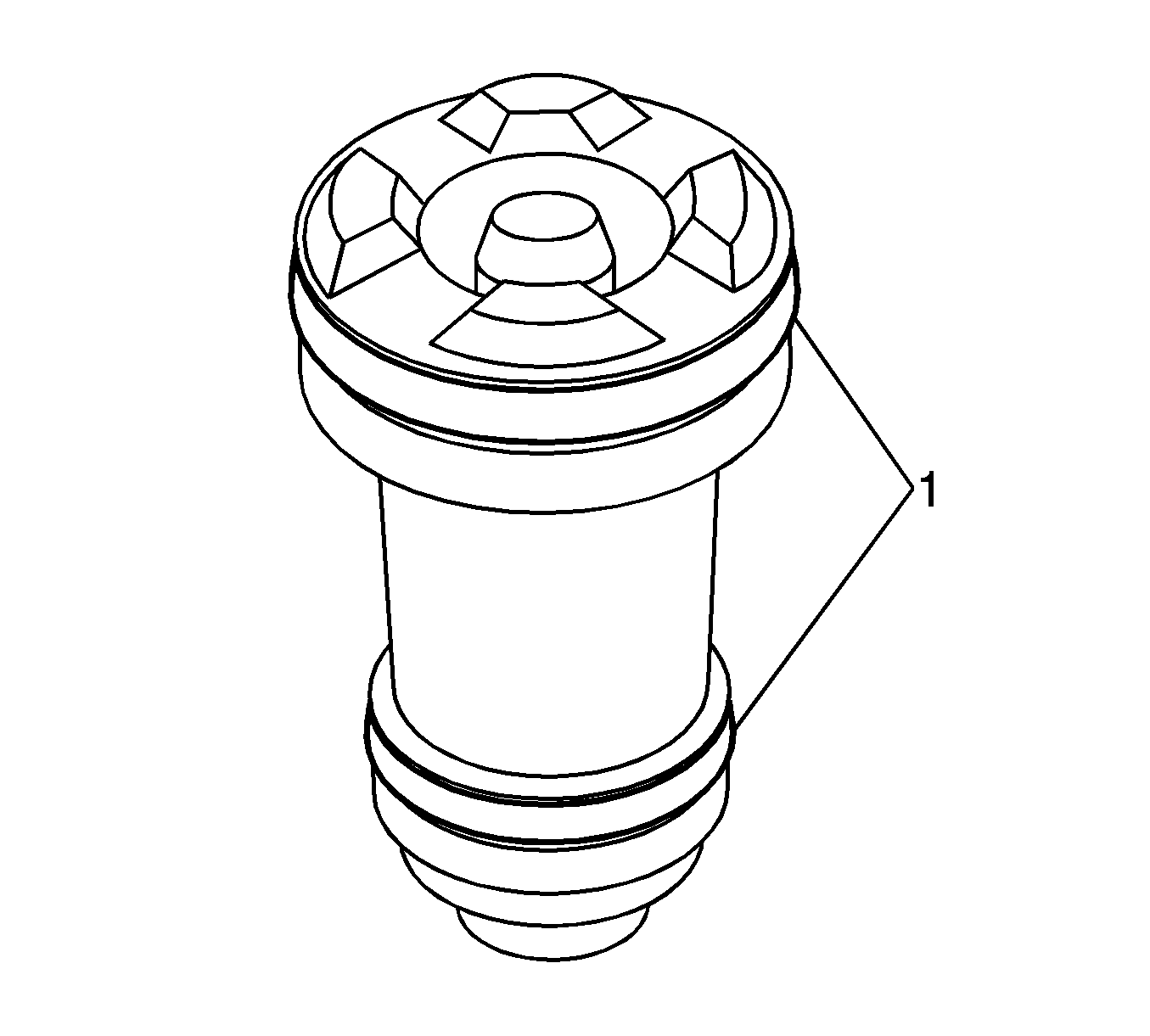
- Remove the 2 O-rings (1) from the direct clutch accumulator piston.
- Apply 392 kPa (57 psi) of compressed air to the oil hole (1) and remove the forward clutch accumulator piston and spring.
- Remove the spring.
- Remove the 2 O-rings (1) from the forward clutch accumulator piston.
- Apply 392 kPa (57 psi) of compressed air to the oil hole (1) and remove the Over Drive (O/D) and 2nd brake clutch accumulator piston and spring.
- Remove the 2 O-rings (1) from the O/D and 2nd brake accumulator piston.
- Remove the bolt and the transaxle wire from the transaxle case.
- Remove the O-ring (1) from the transaxle wire.
- Remove the 16 bolts and tap on the circumference of the transaxle housing with a plastic hammer to remove the transaxle housing from the transaxle case.
- Using a dial indicator, measure the input shaft end play.
- Remove the 6 bolts and oil pump.
- Remove the differential gear assembly from the transaxle case.
- Remove the apply gasket.
- Remove the direct clutch assembly from the transaxle case.
- Remove the thrust needle roller bearing from the direct clutch assembly.
- Remove the direct clutch hub, thrust needle roller bearing and thrust bearing race from the transaxle case.
- Remove the counter driven gear assembly from the transaxle case.
- Remove the 9 bolts and tap on the circumference of the transaxle rear cover with a plastic hammer to remove the transaxle rear cover from the transaxle case.
- Remove the 4 apply gaskets.
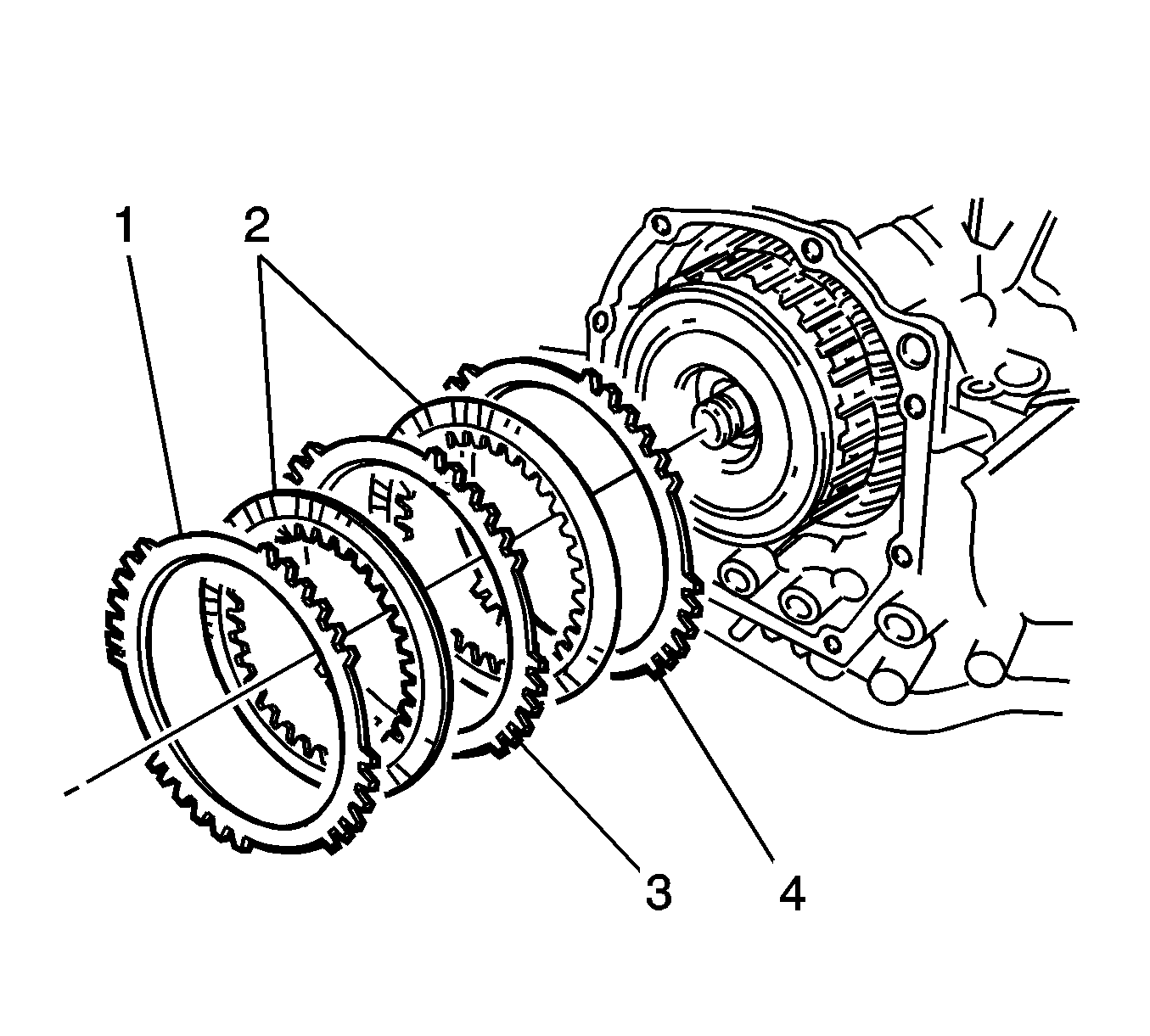
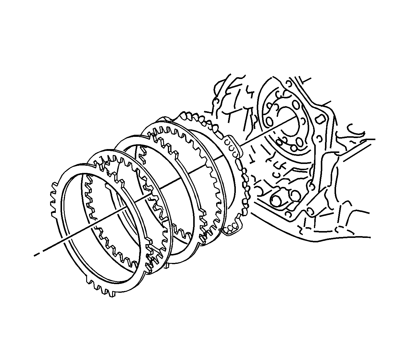
- Remove 2nd coast and O/D brake flange (1), 2 discs (2), and 2 plates (3) from the transaxle case.
- Remove the thrust needle roller bearing and forward and reverse clutch assembly.
- Remove the thrust needle roller bearing and thrust bearing race from the forward and reverse clutch assembly.
- Remove the forward clutch hub from the transaxle case.
- Remove the thrust bearing race and thrust needle roller bearing from the forward clutch hub.
- Remove rear planetary sun gear and 1-way clutch assembly.
- Remove the thrust bearing race from the rear planetary sun gear and 1-way clutch assembly.
- Remove the thrust needle roller bearing and planetary carrier thrust washer from the rear planetary sun gear and 1-way clutch assembly.
- Remove the 1-way clutch assembly and thrust washer from the rear planetary sun gear.
- Remove the front planetary sun gear from the transaxle case.
- Remove the thrust bearing race from the front planetary sun gear.
- Using the DT 46455 (1) and DT 46458 (2), remove the 2 snap rings, 2nd brake piston, and 2nd brake piston return spring.
- Apply 392 kPa (57 psi) of compressed air to the 2nd brake to remove the 2nd brake piston from the 2nd brake clutch cylinder.
- Remove the 2 O-rings (1) from the 2nd brake piston.
- Remove the 2 plates, 2 discs, and flange.
- Remove the No. 2 1-way clutch and planetary gear from the transaxle case.
- Remove the No. 2 1-way clutch from the planetary gear and remove the anti-rattle clip.
- Fix the counter drive gear with the parking lock pawl.
- Remove the planetary ring gear nut using planetary ring gear nut removal/installation socket DT 46472 (1).
- Remove the 2 bolts and parking lock pawl bracket.
- Remove the parking lock pawl shaft, torsion spring and parking lock pawl.
- Remove the bolt and manual detent spring.
- Using a chisel and hammer, unstake and remove the spacer.
- Using a pin punch and hammer, drive out the pin.
- Remove the manual valve lever shaft and manual valve lever.
- Remove the parking lock rod from the manual valve lever.
- Using a screwdriver, remove the oil seal.
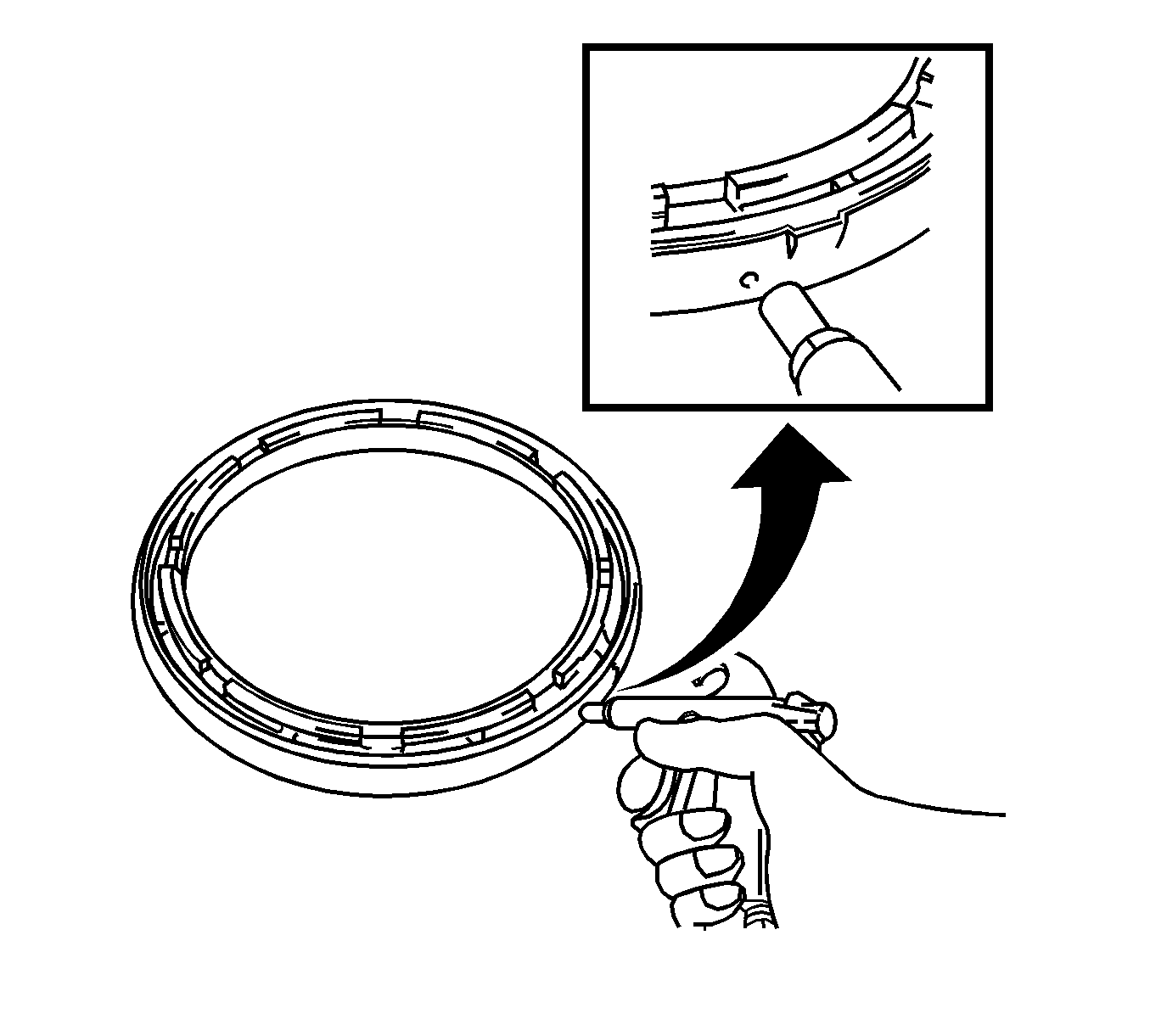
- Using the DT 46455 (2), DT 46457 (3), and DT 46459 (1), remove the planetary ring gear.
- Install the 3 bolts to the counter drive gear.
- Rotate 3 bolts in order and remove the counter drive gear and planetary ring gear.
- Using the DT 46455 (1) and DT 46457 (2), remove the snap ring of 1st and reverse brake.
- Remove the flange, 4 discs, 4 plates, and return spring.
- Apply 392 kPa (57 psi) of compressed air to the transaxle case to remove the 1st and reverse brake piston.
- Remove the 2 O-rings (1) from the 1st and reverse brake piston.
- Remove the bolt and No. 1 transaxle case plate from the transaxle case.
- Using a suitable puller, remove the counter driven gear outer tapered roller bearing race and shim from the transaxle case.
- Using a driver, remove the oil seal from the transaxle case.
- Using the DT 46463 (2) and DT 46465 (1), remove the transaxle case side bearing outer race and shim.
- Remove the 3 bolts and oil reservoir lock plate from the transaxle housing.
- Remove the bolt and No. 1 transaxle apply pipe clamp from the transaxle housing.
- Remove the transaxle lube apply pipe and differential gear lube apply pipe from the transaxle housing.
- Using a suitable puller, remove the counter driven gear outer tapered roller bearing race from the transaxle housing.
- Using a driver, remove the oil seal from the transaxle housing.
- Using a suitable puller, remove the side bearing outer race from the transaxle housing.
- Using the DT 46451 (1),DT 46454 (2) and a driver, remove the snap ring.
- Remove the O/D brake return spring.
- Apply 392 kPa (57 psi) of compressed air to the transaxle rear cover to remove the O/D brake piston.
- Remove the 2 O-rings (1) from the O/D brake piston.
- Remove the 2 seal rings from the transaxle rear cover.
- Remove the 4 screw plugs and 4 O-rings from the transaxle rear cover.





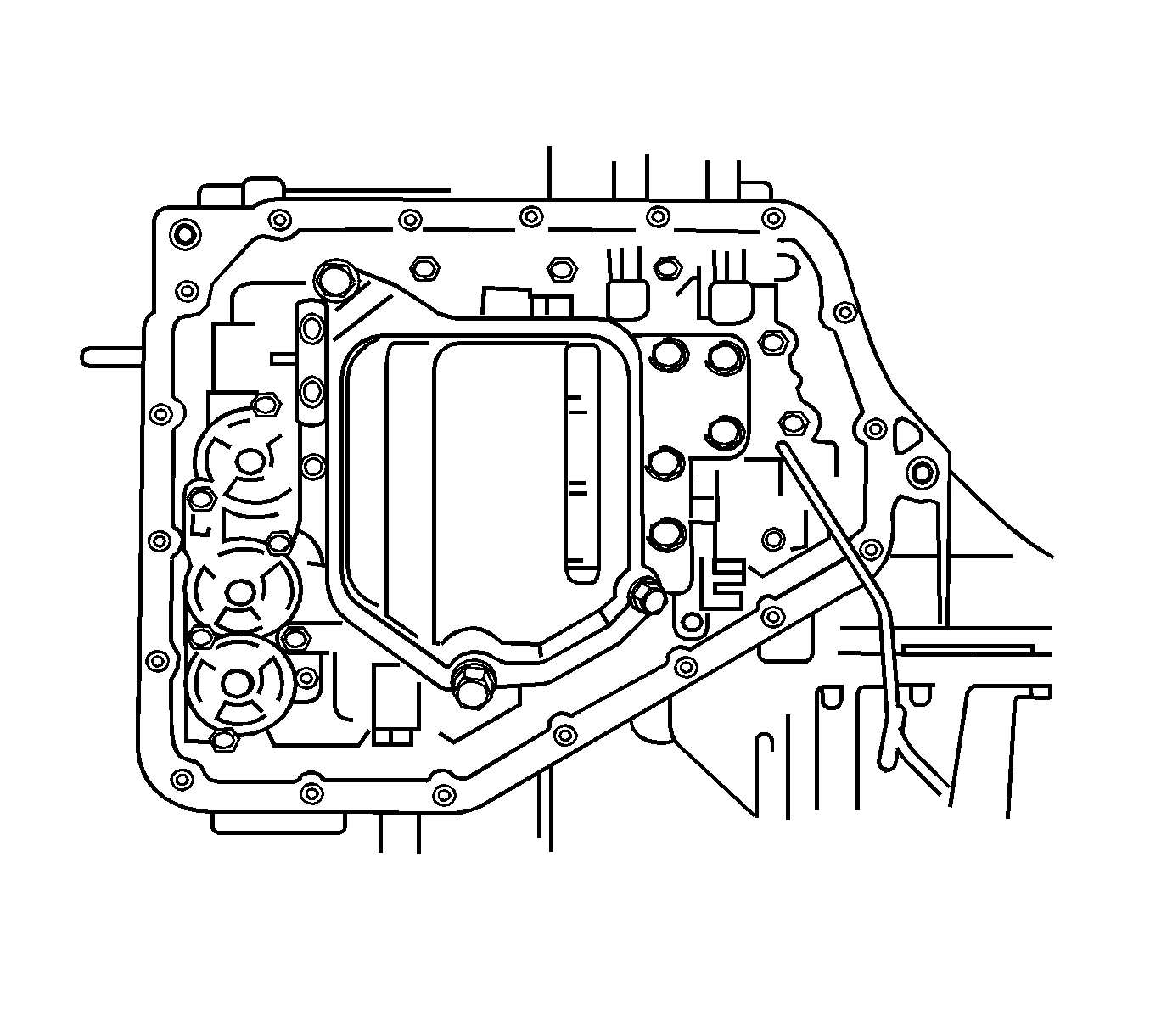


| • | Lock-up control solenoid (5) |
| • | Pressure control solenoid (1) |
| • | No. 2 shift solenoid (2) |
| • | No. 1 shift solenoid (3) |
| • | Timing solenoid (4) |


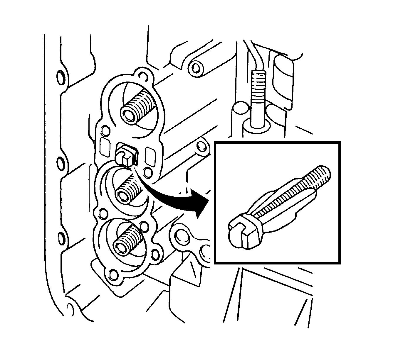

Notice: Refer to Compressed Air Should Not Exceed 98 kPa (14 psi) Notice in the Preface section.

Important: Air pressure may cause the pistons to jump out. When removing the piston, hold it in place with your hand using a waste cloth.
Important: Take care not to splash automatic transaxle fluid (ATF) when air-blowing.

Notice: Refer to Compressed Air Should Not Exceed 98 kPa (14 psi) Notice in the Preface section.

Important: Air pressure may cause the pistons to jump out. When removing the piston, hold it in place with your hand using a waste cloth.
Important: Take care not to splash automatic transaxle fluid (ATF) when air-blowing.

Notice: Refer to Compressed Air Should Not Exceed 98 kPa (14 psi) Notice in the Preface section.

Important: Air pressure may cause the pistons to jump out. When removing the piston, hold it in place with your hand using a waste cloth.
Important: Take care not to splash automatic transaxle fluid (ATF) when air-blowing.


Important: Be careful not to drop the differential gear assembly when the transaxle housing is removed.

Specification
The end play is 0.3-0.9 mm (0.012-0.035 in).




Notice: Refer to Compressed Air Should Not Exceed 98 kPa (14 psi) Notice in the Preface section.
Notice: Refer to Transaxle Case Damage Notice in the Preface section.

Notice: Refer to Compressed Air Should Not Exceed 98 kPa (14 psi) Notice in the Preface section.
Important: Air pressure may cause the pistons to jump out. When removing the piston, hold it in place with your hand using a waste cloth.
Important: Take care not to splash automatic transaxle fluid (ATF) when air-blowing.

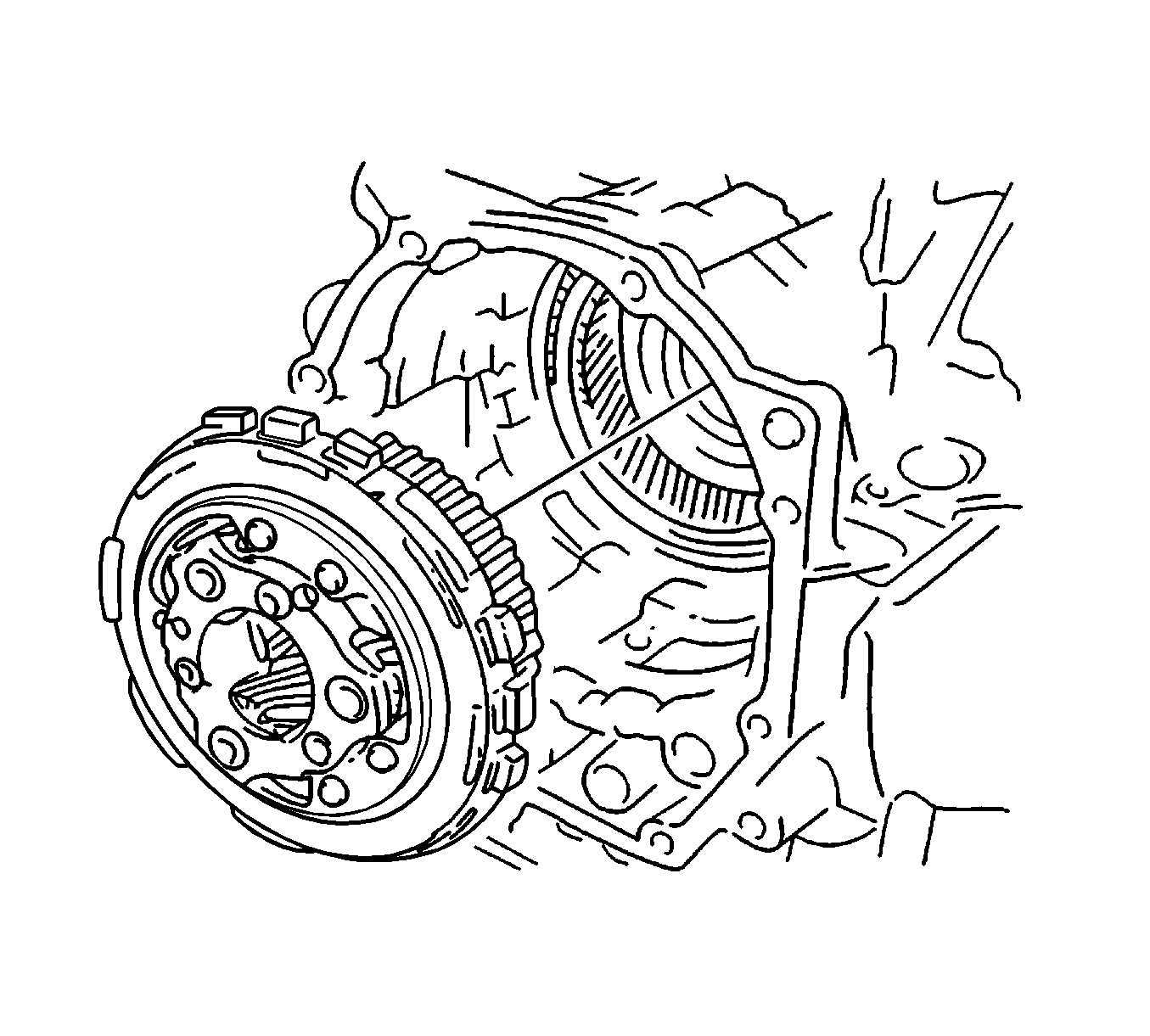


Notice: Do not chisel and remove the planetary ring gear nut staking before removing the nut. Damage to the planetary ring gear could result if force is applied . Remove the nut without unstaking the planetary ring gear. If force is used to unstake the planetary ring gear nut, damage the bearing could result.
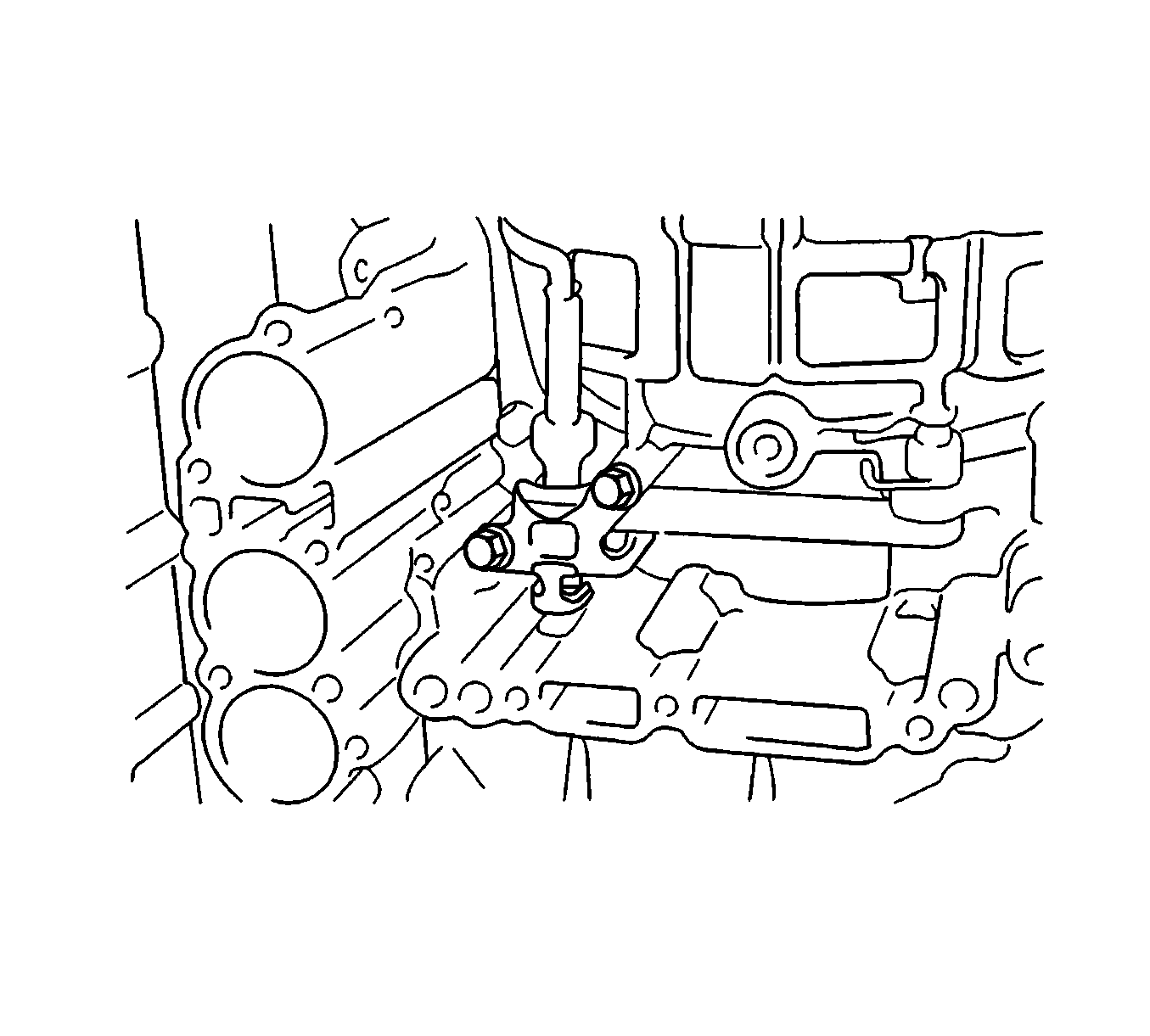


Specification
| • | The bolt (M6) L is equal to 40-80 mm (1.57-3.15 in). |
| • | The bolt (M6) pitch is equal to 1.0 mm (0.04 in). |

Caution: Use extreme care when removing snap rings. Always wear adequate eye protection in order to avoid personal injury.

Notice: Refer to Compressed Air Should Not Exceed 98 kPa (14 psi) Notice in the Preface section.

Important: Air pressure may cause the pistons to jump out. When removing the piston, hold it in place with your hand using a waste cloth.
Important: Take care not to splash automatic transaxle fluid (ATF) when air-blowing.


Notice: Refer to Brake Piston Is Lowered Notice in the Preface section.


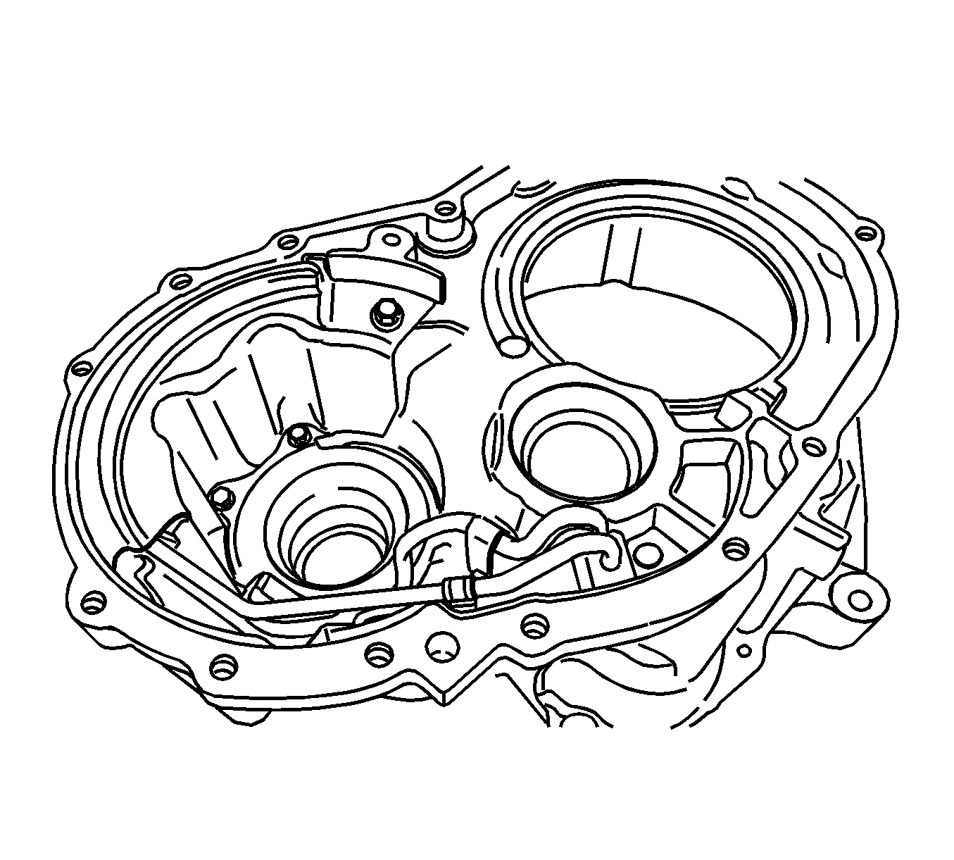
Notice: Refer to Brake Piston Is Lowered Notice in the Preface section.
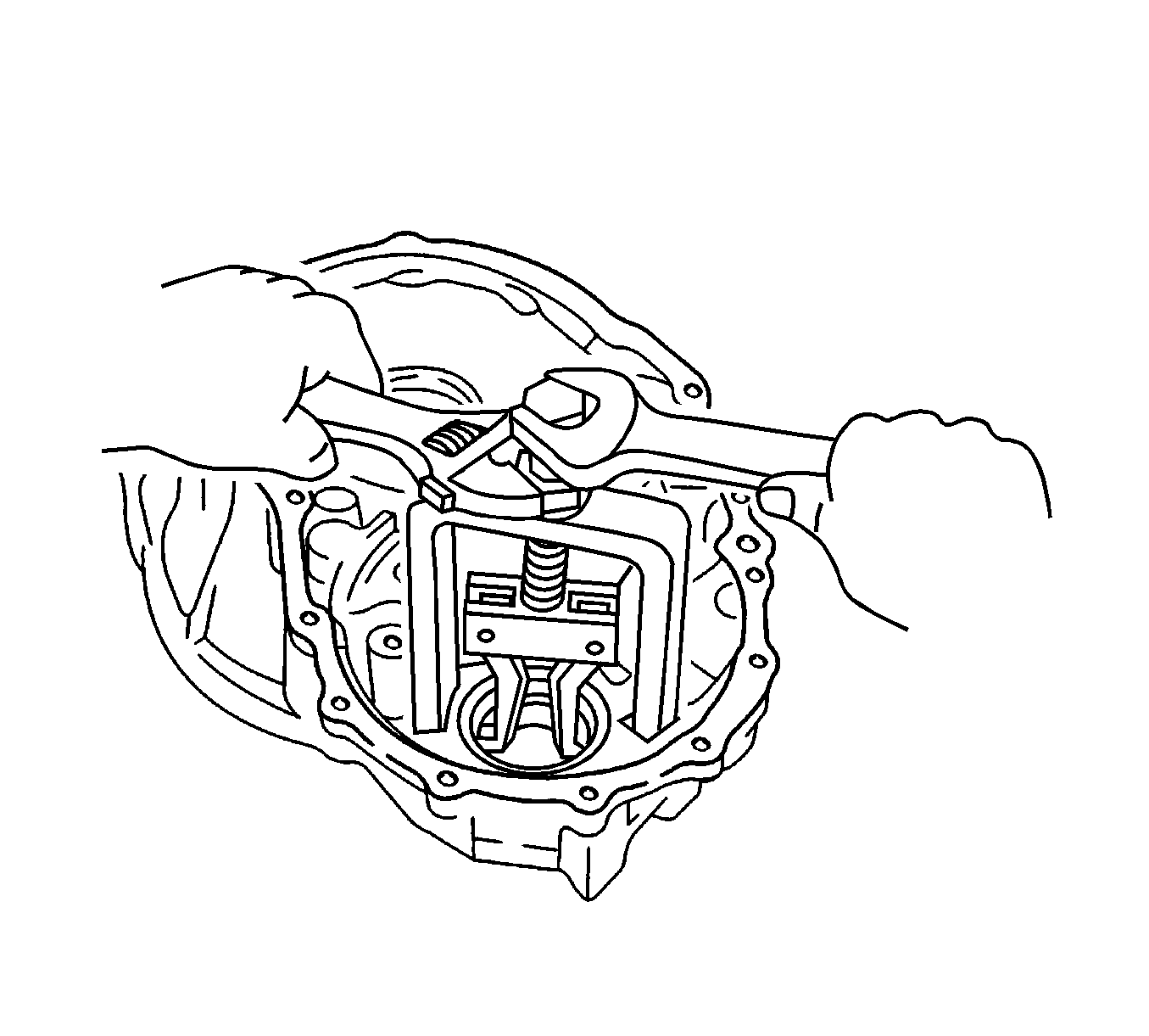
Notice: Refer to Transaxle Case Damage Notice in the Preface section.

Caution: Use extreme care when removing snap rings. Always wear adequate eye protection in order to avoid personal injury.

Notice: Refer to Compressed Air Should Not Exceed 98 kPa (14 psi) Notice in the Preface section.

Important: Air pressure may cause the pistons to jump out. When removing the piston, hold it in place with your hand using a waste cloth.
Important: Take care not to splash automatic transaxle fluid (ATF) when air-blowing.
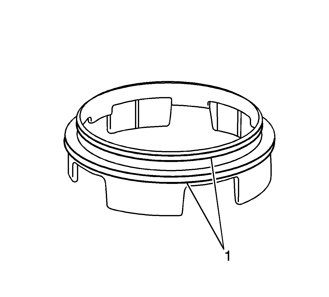
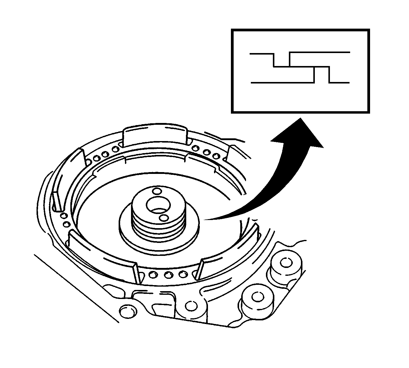
Important: Do not expand the seal ring excessively.

