GM Service Manual Online
For 1990-2009 cars only
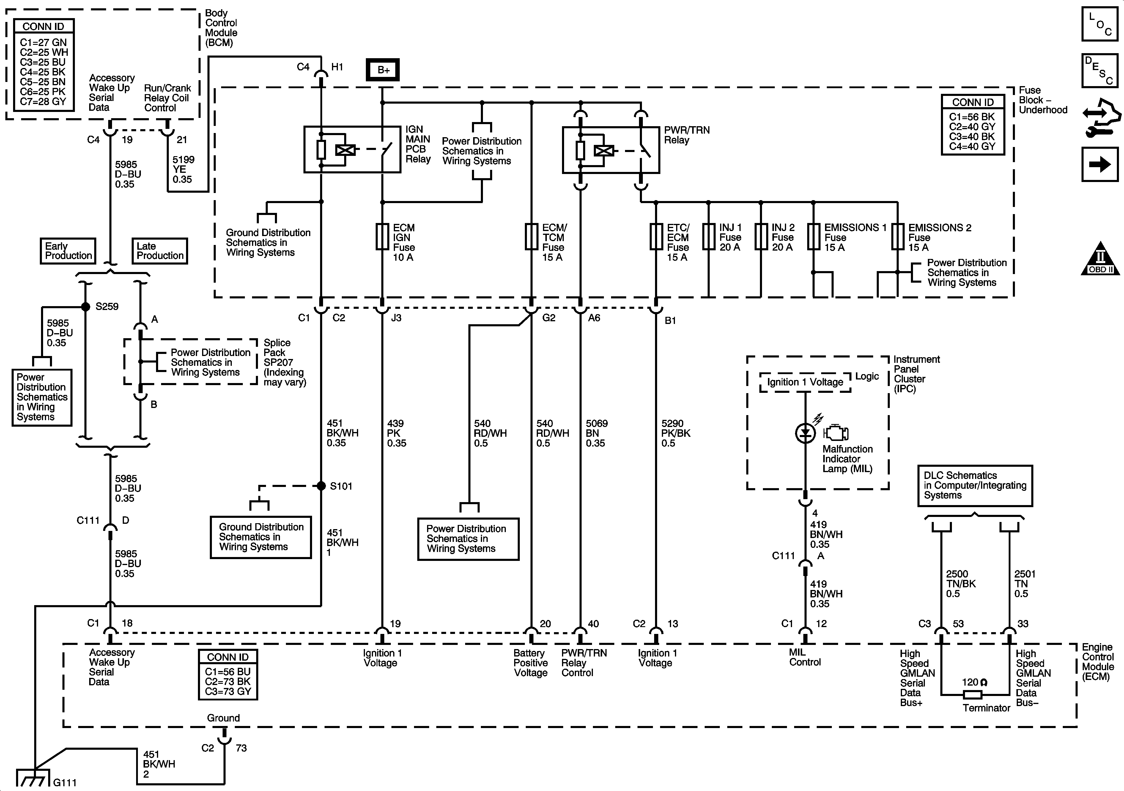
Figure 1:

ECM Power, Ground, MIL, and Serial Data

Object Number: 1648489  Size: FS
Master Electrical Component List
Engine Control Module Description
Control Module References
5-Volt and Low Reference Bussing
Engine Controls Schematic Icons
Fuse Block - Underhood Bussing
G101, G102, G111, and G112 (LS4)
Fuse Block - Underhood Bussing
EMISSIONS 1, EMISSIONS 2, A/C CMPRSR Fuses, A/C CMPRSR, FAN 1, FAN 2, and FAN 3 Relays
Ignition Switch
Ignition Switch
G101, G102, G111, and G112 (LS4)
INT LTS/PNL DIM, LT T/SIG RT T/SIG, CHMSL/BACKUP, INT LIGHTS, RVC SEN, and ECM/TCM Fuses
High Speed GMLAN Serial Data
G101, G102, G111, and G112 (LS4)
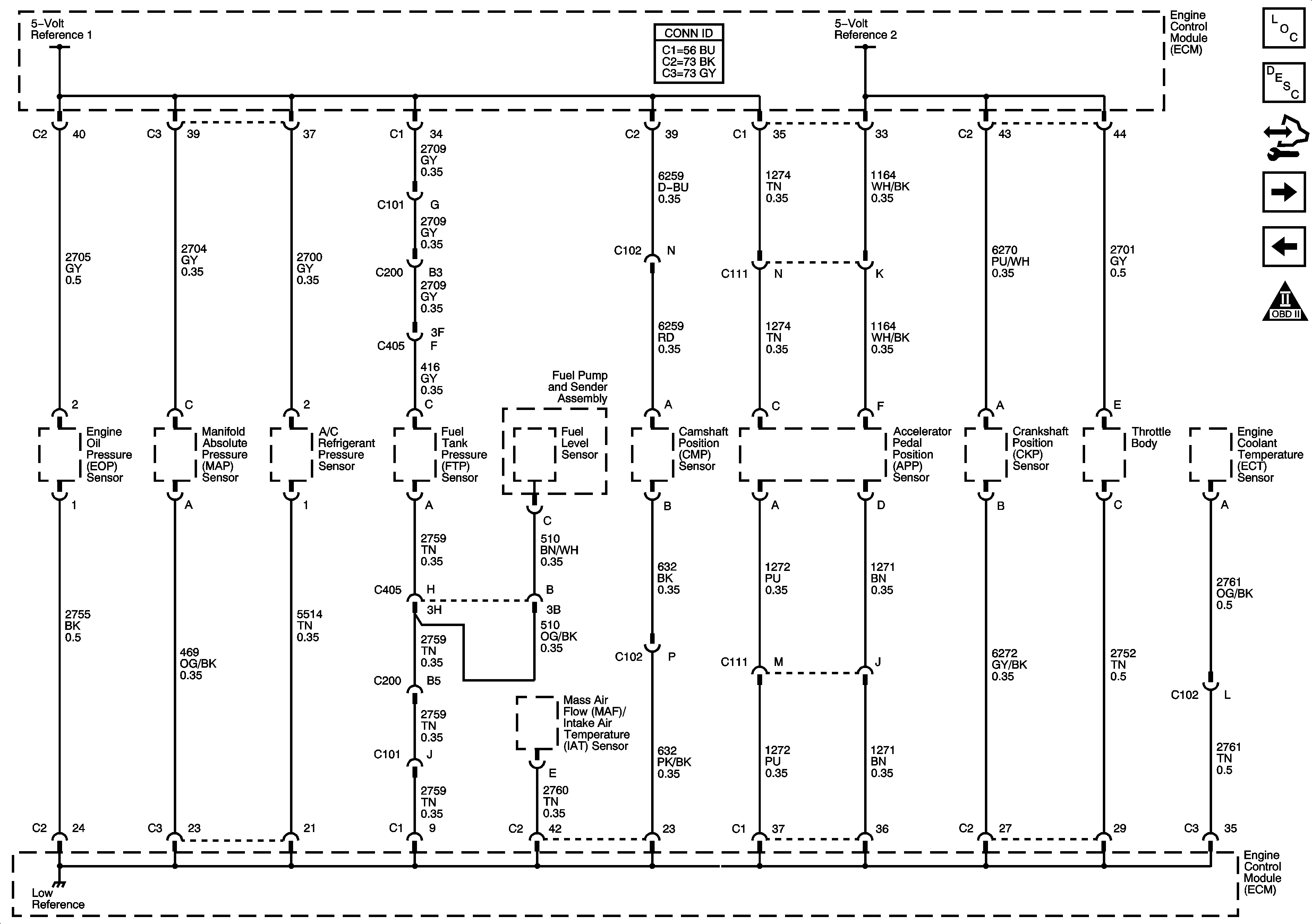
Figure 2:

5-Volt and Low Reference Bussing


Object Number: 1648492  Size: FS
Master Electrical Component List
Engine Control Module Description
Control Module References
MAF/IAT, MAP, and ECT Sensors
ECM Power, Ground, MIL, and Serial Data
Engine Controls Schematic Icons
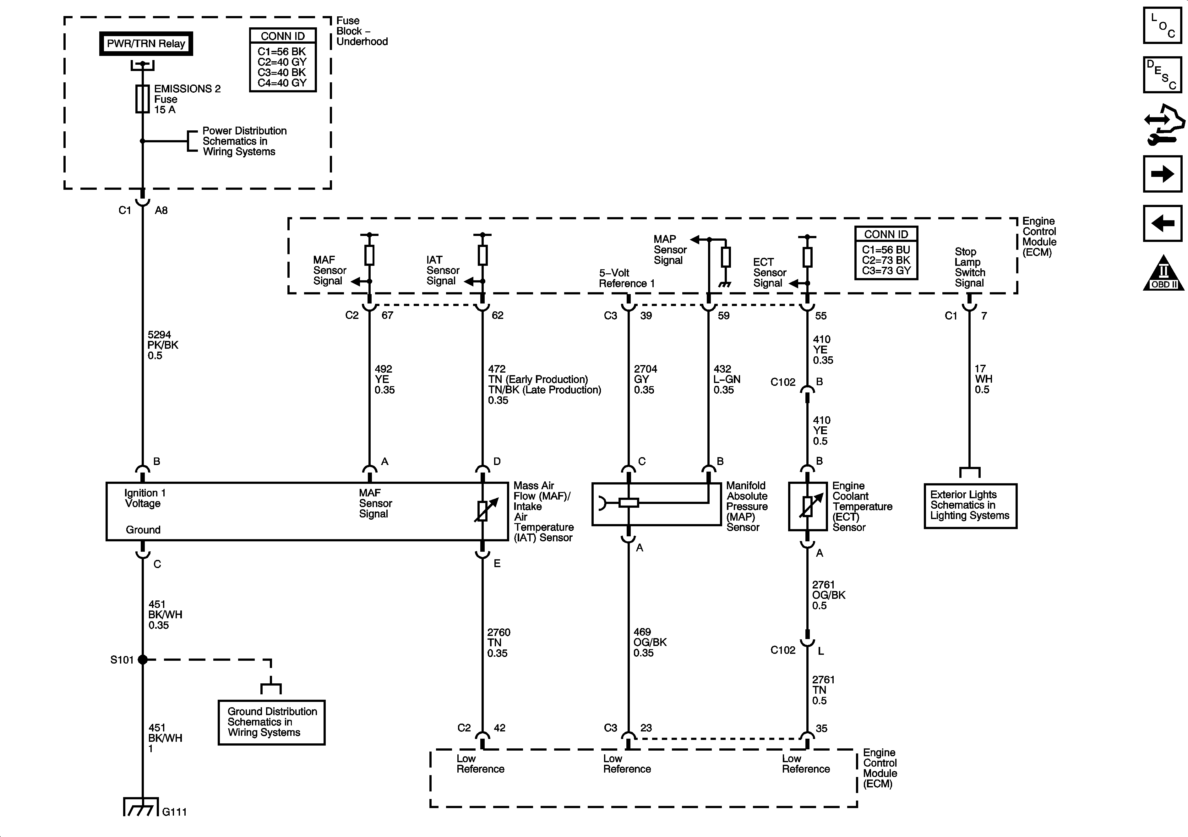
Figure 3:

MAF/IAT, MAP, and ECT Sensors


Object Number: 1648502  Size: FS
Master Electrical Component List
Engine Control Module Description
Control Module References
Heated Oxygen Sensors
5-Volt and Low Reference Bussing
Engine Controls Schematic Icons
ECM Power, Ground, MIL, and Serial Data
EMISSIONS 1, EMISSIONS 2, A/C CMPRSR Fuses, A/C CMPRSR, FAN 1, FAN 2, and FAN 3 Relays
Turn Signal, Hazard, and Stoplamps Outputs
G101, G102, G111, and G112 (LS4)
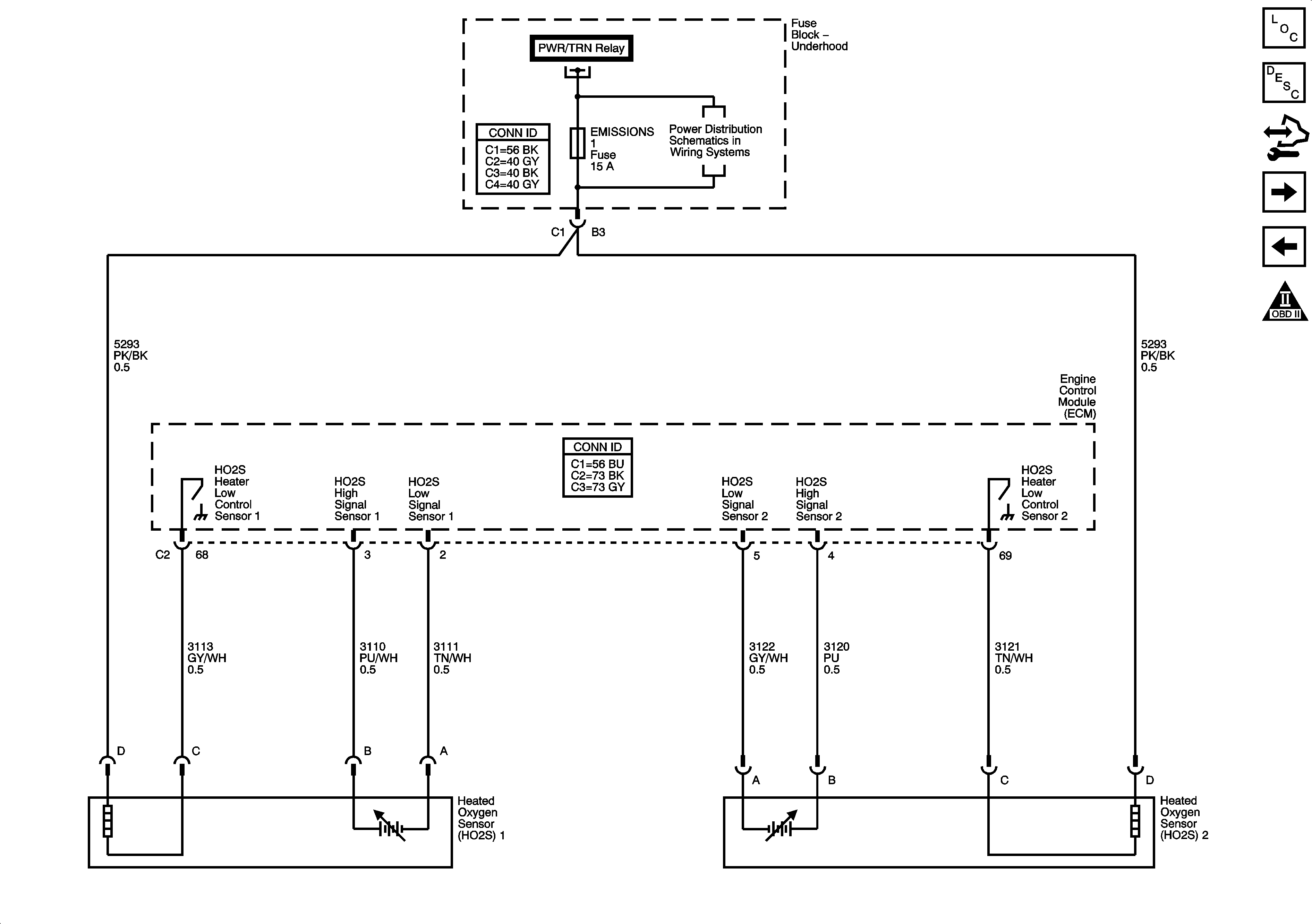
Figure 4:

Heated Oxygen Sensors


Object Number: 1648508  Size: FS
Master Electrical Component List
Engine Control Module Description
Control Module References
Electronic Throttle Controls
MAF/IAT, MAP, and ECT Sensors
Engine Controls Schematic Icons
ECM Power, Ground, MIL, and Serial Data
EMISSIONS 1, EMISSIONS 2, A/C CMPRSR Fuses, A/C CMPRSR, FAN 1, FAN 2, and FAN 3 Relays
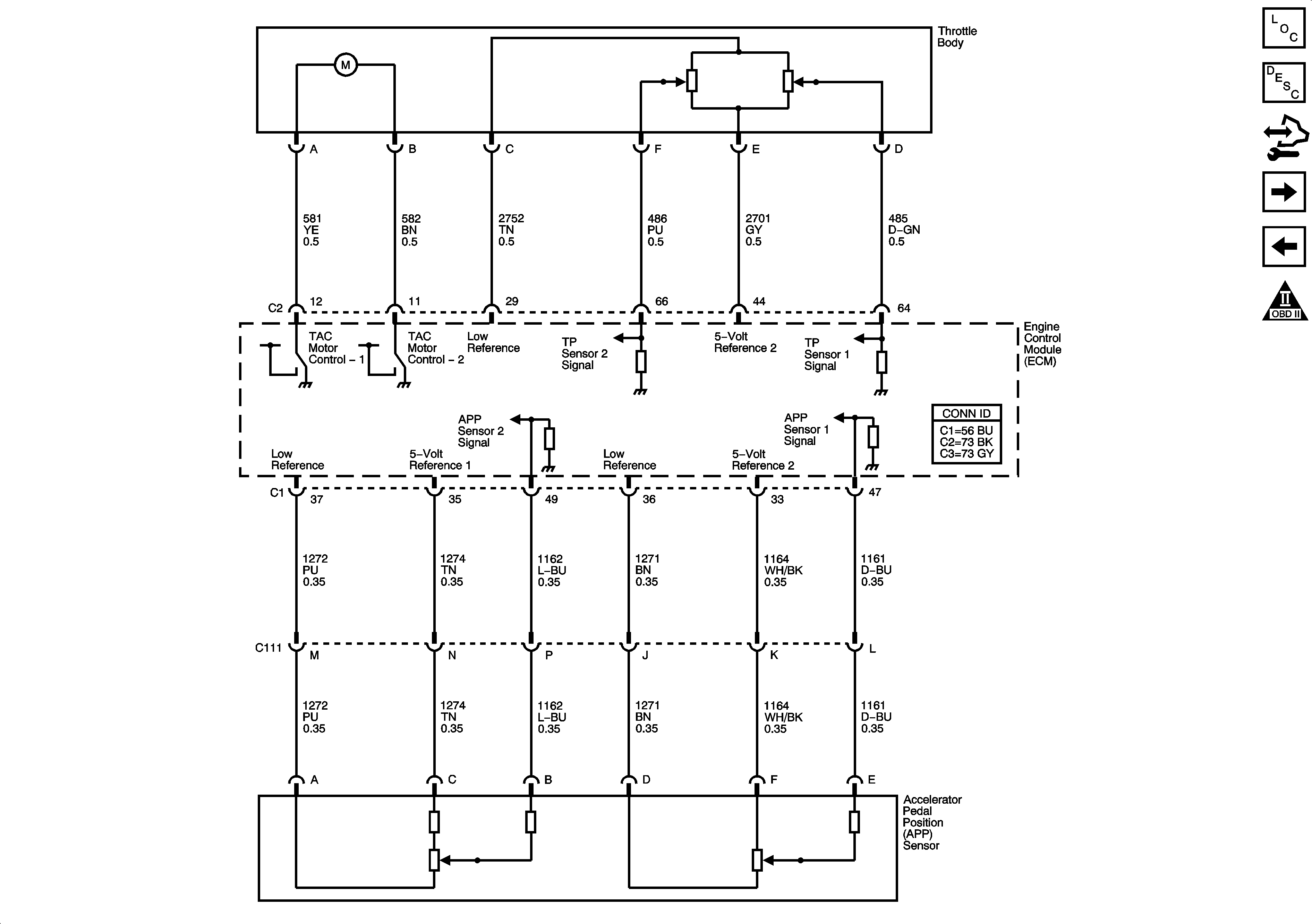
Figure 5:

Electronic Throttle Controls


Object Number: 1648509  Size: FS
Master Electrical Component List
Throttle Actuator Control (TAC) System Description
Control Module References
Fuel Injectors, and Fuel Pump Controls
Heated Oxygen Sensors
Engine Controls Schematic Icons
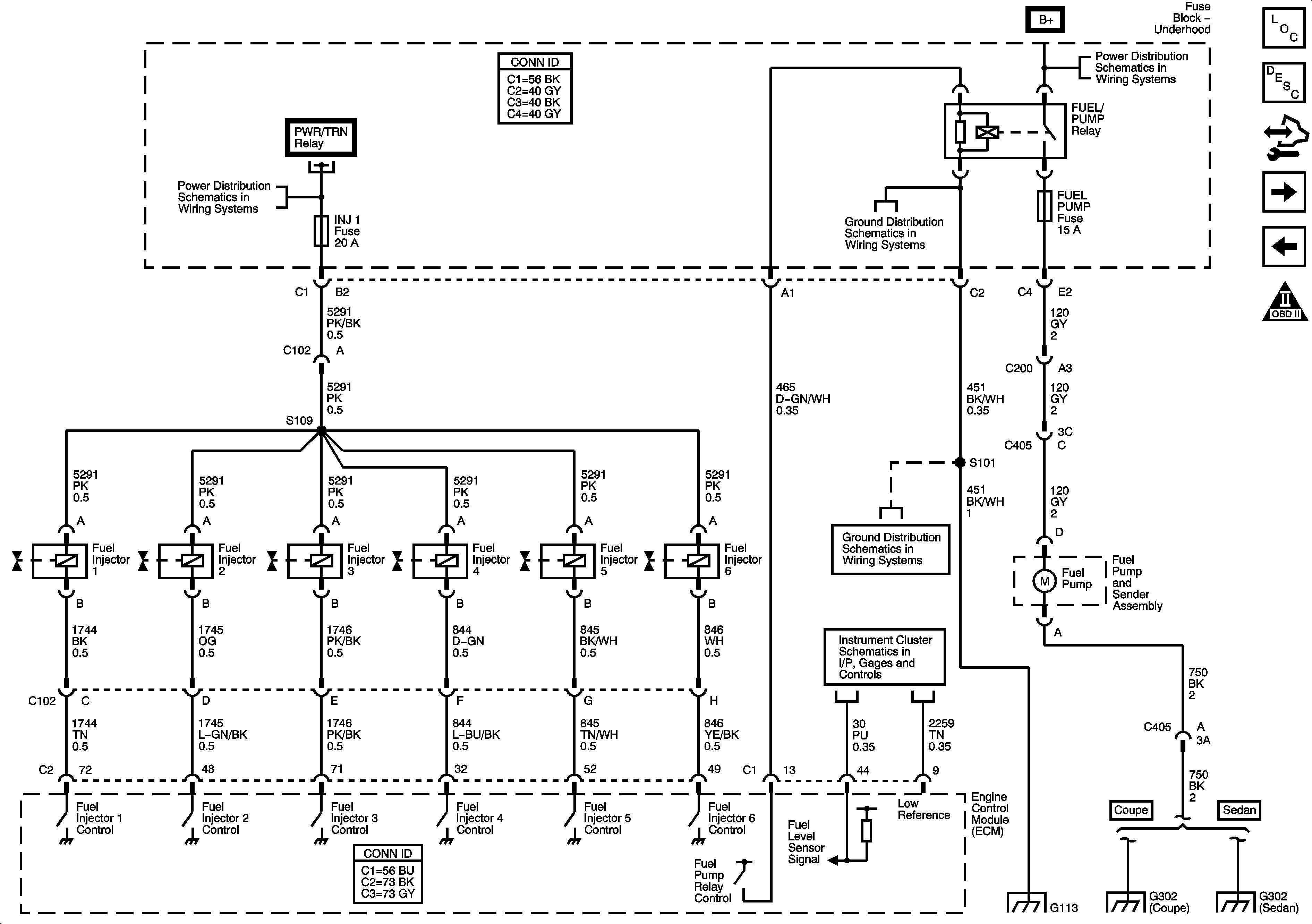
Figure 6:

Fuel Injectors, and Fuel Pump Controls


Object Number: 1648510  Size: FS
Master Electrical Component List
Fuel System Description
Control Module References
EVAP Solenoids, IMT Solenoid, and FTP Sensor
Electronic Throttle Controls
Engine Controls Schematic Icons
Fuse Block - Underhood Bussing
ECM Power, Ground, MIL, and Serial Data
ETC/ECM, INJ 1, INJ 2 Fuses (LZE, LZ4, LZ9)
G113, and G115
G113, and G115
Power, Ground, and Gages
G113, and G115
G302
G302 (Sedan)
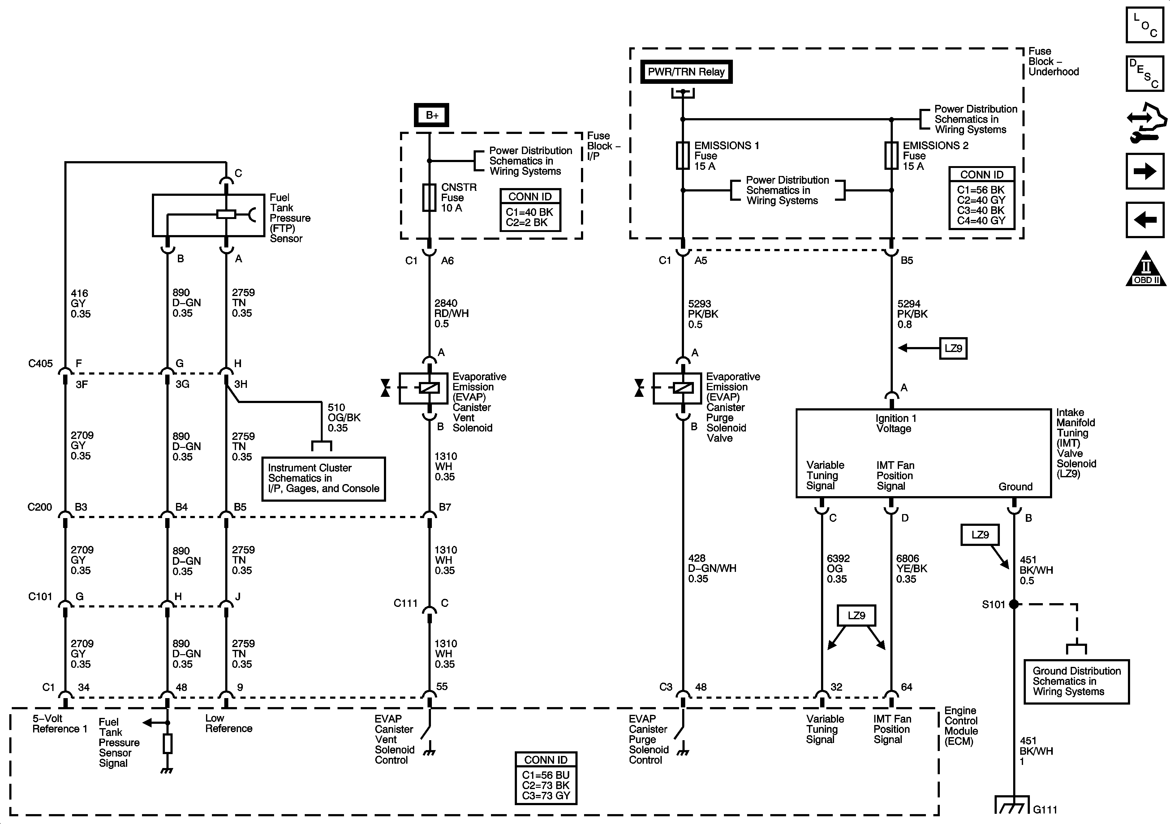
Figure 7:

EVAP Solenoids, IMT Solenoid, and FTP Sensor


Object Number: 1648512  Size: FS
Master Electrical Component List
Evaporative Emission Control System Description
Control Module References
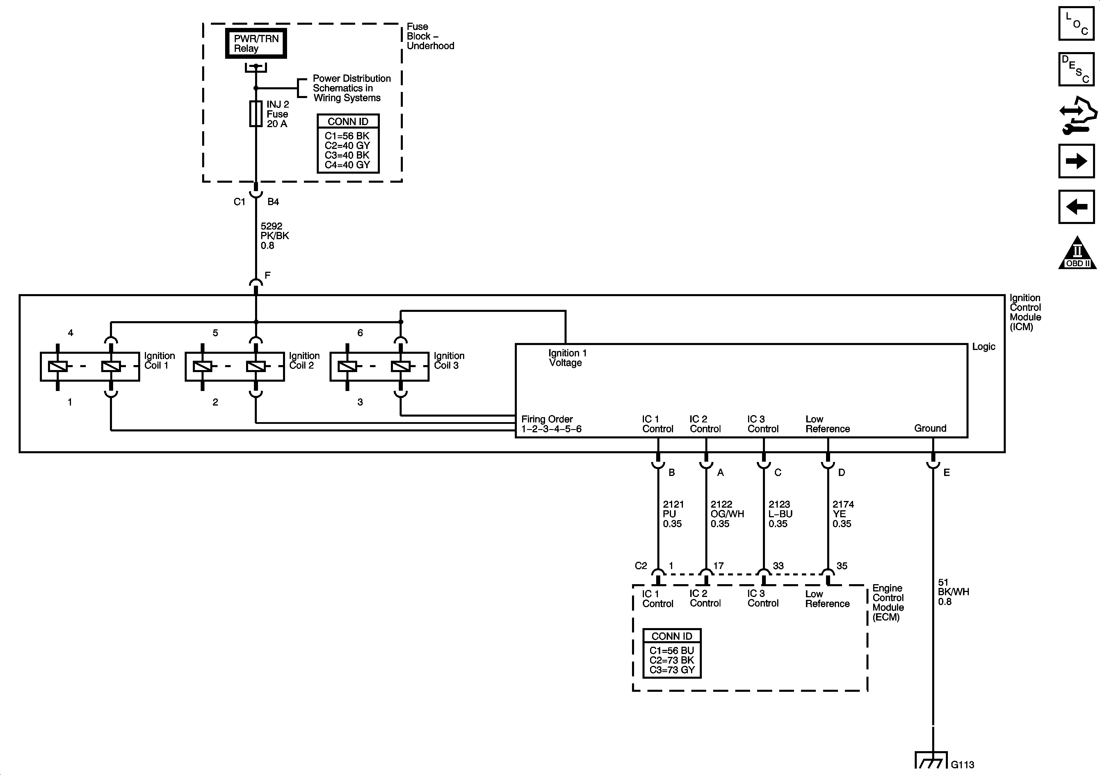
Ignition Control Module
Fuel Injectors, and Fuel Pump Controls
Engine Controls Schematic Icons
BATT 1, CNSTR, ONSTAR, AMP, and AUX Fuses
ECM Power, Ground, MIL, and Serial Data
Fuse Block - Underhood Bussing
EMISSIONS 1, EMISSIONS 2, A/C CMPRSR Fuses, A/C CMPRSR, FAN 1, FAN 2, and FAN 3 Relays
Power, Ground, and Gages
G101, G102, G111, and G112 (LS4)
Figure 8:

Ignition Control Module


Object Number: 1648518  Size: FS
Master Electrical Component List
Electronic Ignition (EI) System Description
Control Module References
Camshaft, Crankshaft, Knock Sensors, and Camshaft Position Actuator Solenoid
EVAP Solenoids, IMT Solenoid, and FTP Sensor
Engine Controls Schematic Icons
ECM Power, Ground, MIL, and Serial Data
ETC/ECM, INJ 1 and INJ 2 Fuses (LS4)
G113, and G115
Figure 9:

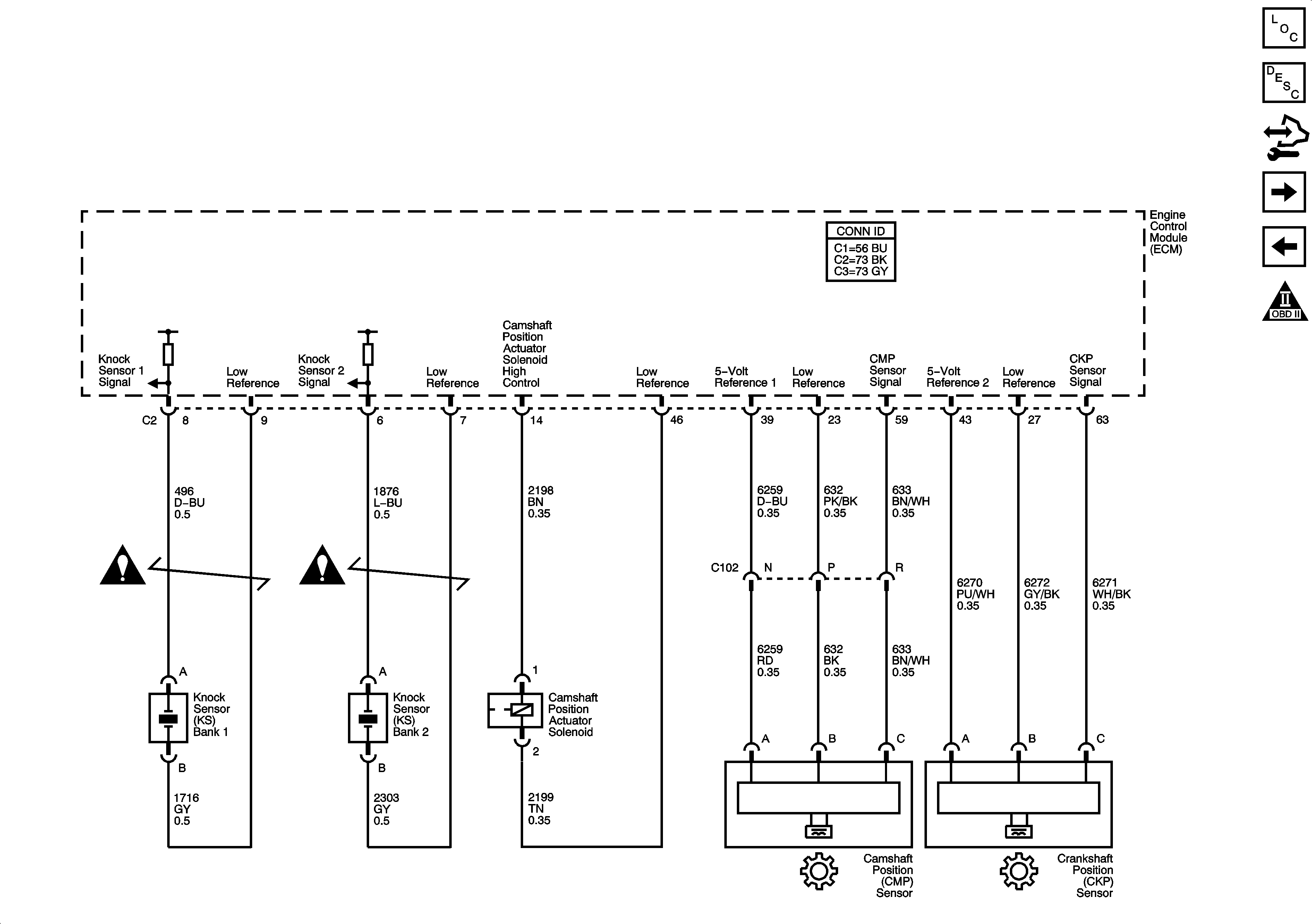
Camshaft, Crankshaft, Knock Sensors, and Camshaft Position Actuator Solenoid


Object Number: 1648528  Size: FS
Master Electrical Component List
Camshaft Actuator System Description
Control Module References
Controlled/Monitored Subsystem References
Ignition Control Module
Engine Controls Schematic Icons
Figure 10:

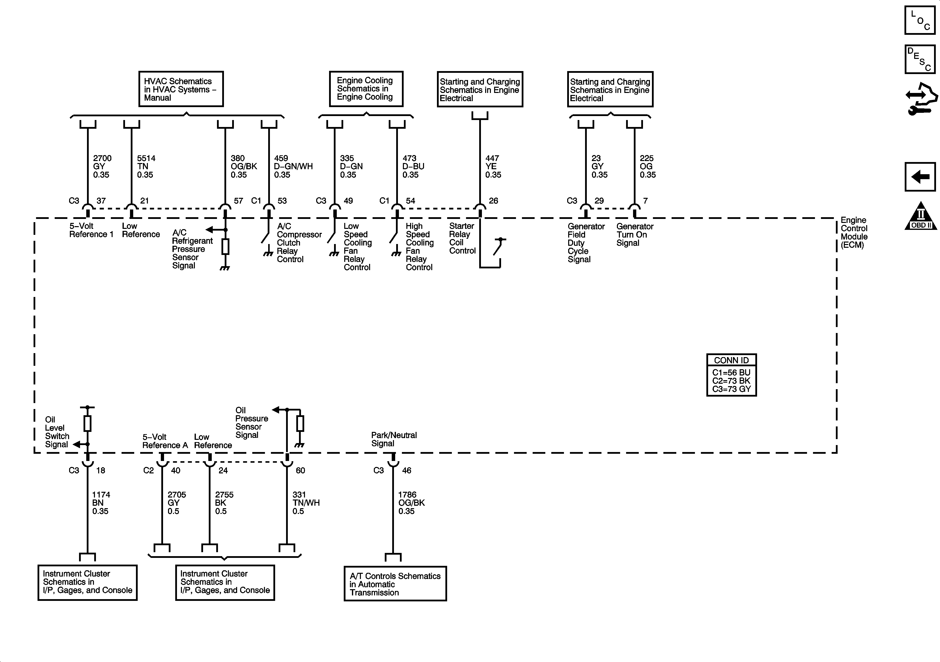
Controlled/Monitored Subsystem References


Object Number: 1648539  Size: FS
Master Electrical Component List
Engine Control Module Description
Control Module References
Camshaft, Crankshaft, Knock Sensors, and Camshaft Position Actuator Solenoid
Engine Controls Schematic Icons
A/C Compressor Controls
Engine Cooling Schematics
Starter
Generator
Driver Information Center
Indicators
PRNDL, and IMS Switch