BACK GLASS ASSEMBLY SERVICE PROCEDURE

BACK GLASS ASSEMBLY SERVICE PROCEDURE (Revised to change step 8 and add step 24.)
VEHICLES AFFECTED: 1987 MONTE CARLO SS AEROCOUPE -----------------
SERVICE MANUAL UPDATE
The 1987 Monte Carlo SS Aerocoupe features a prominate back glass assembly which has three sides and an attached perimeter weatherstrip.
Because of the limited number of Aerocoupes built, a service procedure for the back glass was not shown in the service manual.
Therefore, when service is required, the following back glass removal and replacement procedure should be used as reference.
PROCEDURE
Refer to Section 2, stationary glass, GM Body Service Manual, for information on Adhesive Service Kit, P/N 993110, short and extended methods of installation, and tools needed before continuing with the following procedures.
To prevent damage, protect exterior areas around back glass and interior rear seat and trim.
Remove or Disconnect
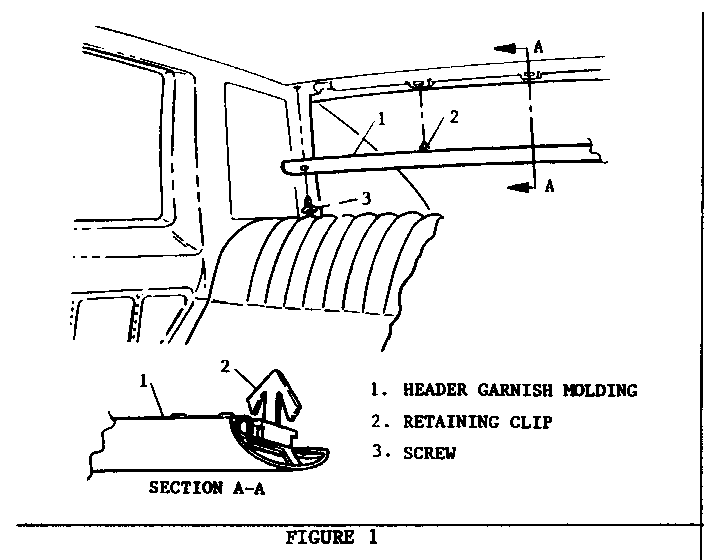
1. Inside the vehicle: Screws, rear header garnish molding to roof (Figure 1).
2. Retaining clips, rear header garnish molding to roof (Figure 1).
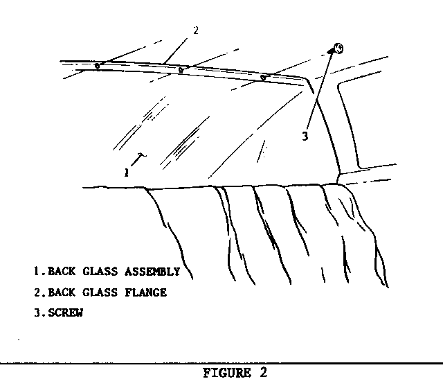
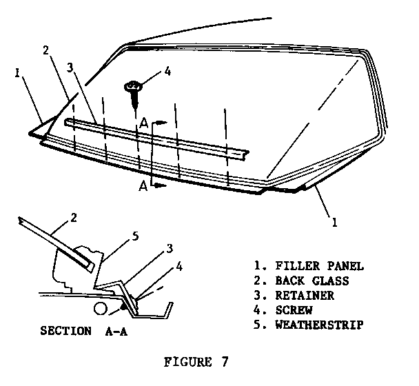
3. Screws, back glass weatherstrip to back glass-flange (Figures 2 and 7).
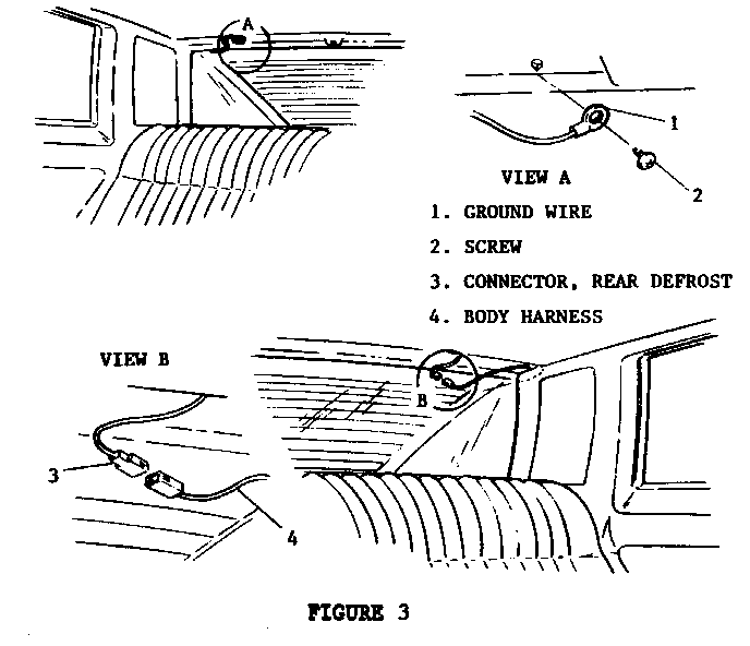
4. Screw, ground wire to vehicle (rear defroster on back glass only) (Figure 3).
5. Wiring connector of rear defroster from vehicles body harness (Figure 3).
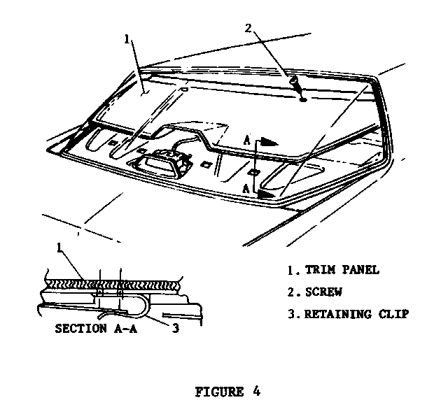
6. Screws, rear seat to back glass trim panel (Figure 4).
7. Rear seat to back glass trim panel by lifting out and up to release four (4) retaining clips from vehicle (Figure 4).
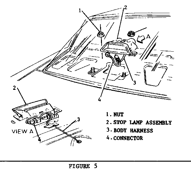
8. Nuts, center high-mounted stop lamp assembly to vehicle and wiring connector to body harness (Figure 5).
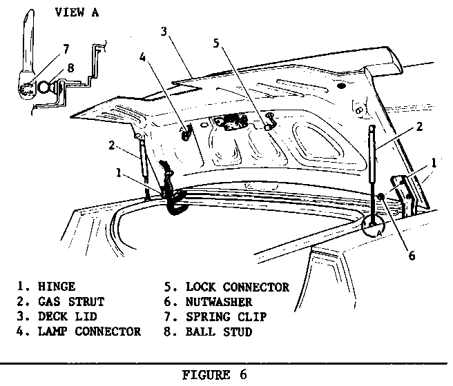
9. Trunk lamp and deck lid lock assembly wire harness connectors (Figure 6).
10. Wire harness from deck lid access and routing holes (Figure 6).
11. Gas struts by prying bottom ball studs from spring clip Figure 6).
12. While helper supports deck lid, attaching hinge nuts to deck lid (Figure 6).
13. Deck lid (Figure 6).
14. Outside vehicle: Screws securing lower back glass retainer to vehicle (Figure 7).
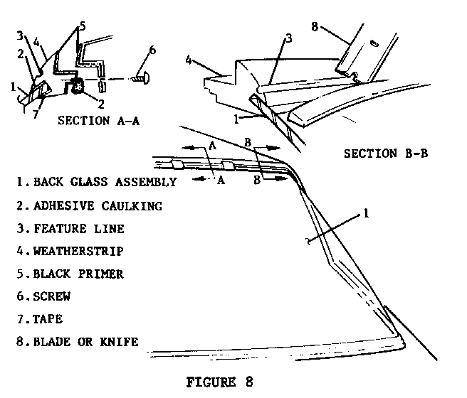
15. Using a razor blade or utility knife make a preliminary cut into weatherstrip at feature line (Figure 8) around entire perimeter of glass, staying as close to edge of glass as possible.
NOTICE: GLASS REMOVAL REQUIRES THREE PEOPLE, ONE PERSON INSIDE OF VEHICLE PUSHING OUTWARD ON GLASS AND TWO PEOPLE SUPPORTING GLASS FROM OUTSIDE.
Clean
Weatherstrip and urethane sealer from back glass opening using a scrapper or equivalent tool. This is an extremely important step, all sealer and weatherstrip must be removed from the vehicle's surface to insure proper sealing of new unit. When using solvents, be sure to follow manufacturer's directions.
Surface of glass where adhesive and tape are to be applied (only if weatherstrip is to be replaced).
Install or Connect
NOTICE: IF ONLY THE WEATHERSTRIP AROUND THE GLASS IS TO BE REPLACED, AFTER CLEANING, APPLY (12 mm) 1/2 INCH BUTYL TAPE TO INNER SURFACE OF GLASS AND ADHESIVE CAULKING THE SAME WIDTH AROUND THE OUTER SURFACE PRIOR T0 INSTALLING WEATHERSTRIP.
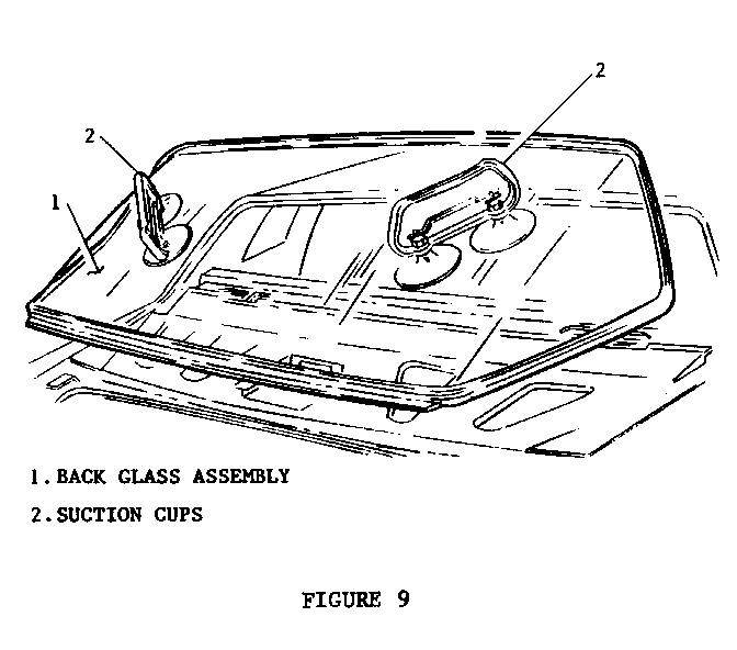
1. With the aid of a helper and suction cups, position (dry fit) glass assembly into back glass opening (Figure 9). With glass in proper position, apply a piece of masking tape over each side of glass assembly and adjacent body pillars or part. Slit tape vertically at vehicle body And weatherstrip junction. During installation, tape on glass assembly can be aligned with tape on body to guide glass into proper position.
2. Remove glass assembly and clean surface of weatherstrip to which adhesive and primer will be applied. (Figure 8).
3. Apply black primer from urethane kit to surface of weatherstrip just cleaned and allow to dry five minutes.
4. Apply black primer to vehicle where glass assembly will mate when installed (if vehicle has been repaired, white primer must be used and let dry before black primer) (Figure 8).
5. Apply a smooth continuous bead (1/2 in. dia.) of adhesive caulking to back glass weatherstrip mating surface (Figure 8).
6. With the aid of helper and suction cups, lift back glass assembly and position in back glass opening (Figure 9).
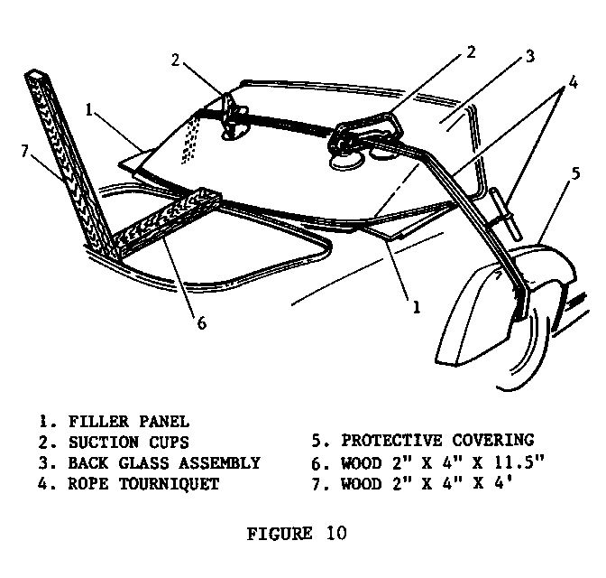
7. Press glass assembly into place using two by four inch pieces of wood cut to size as shown. Push glass and weatherstrip into position to align with vehicle's side panel fillers as shown in Figures 7 and 10.
8. Attach a piece of nylon rope (12 mm or 1/2" diameter x 7 m or 21' long) or equivalent to the rear axle or route through the rear wheel openings. Secure back glass by constructing a rope tourniquet as shown in Figure 10.
9. Screws, lower back glass retainer to vehicle (Figure 7).
10. Screws, weatherstrip to upper back glass opening flange (Figures 2 and 8).
11. Nuts, center high mounted stop lamp and gasket assembly to vehicle back shelf (Figure 5).
12. Wiring connector on stop lamp assembly to vehicles body wiring harness (Figure 5).
13. Retaining clips holding center of rear seat to back glass trim panel to vehicle (Figure 4).
14. Screws, rear seat to back glass trim panel to vehicle (Figure 4).
15. Screw, rear defroster ground wire and defroster connector (Figure 3).
16. Screws, back glass flange inside into weatherstrip on glass (Figures 2 and 7).
17. Retaining clips, rear header garnish molding (Figure 1).
18. Screws, rear header garnish molding to roof (Figure 1).
19. Deck lid with aid of helper.
20. Nuts, hinges to deck lid (Figure 6).
21. Gas struts (Figure 6).
22. Wire harness through access holes (Figure 6).
23. Lock assembly and trunk lamp wire harness connectors (Figure 6).
24. Remove tourniquet after 24 hours.
General Motors bulletins are intended for use by professional technicians, not a "do-it-yourselfer". They are written to inform those technicians of conditions that may occur on some vehicles, or to provide information that could assist in the proper service of a vehicle. Properly trained technicians have the equipment, tools, safety instructions and know-how to do a job properly and safely. If a condition is described, do not assume that the bulletin applies to your vehicle, or that your vehicle will have that condition. See a General Motors dealer servicing your brand of General Motors vehicle for information on whether your vehicle may benefit from the information.
