Tools Required
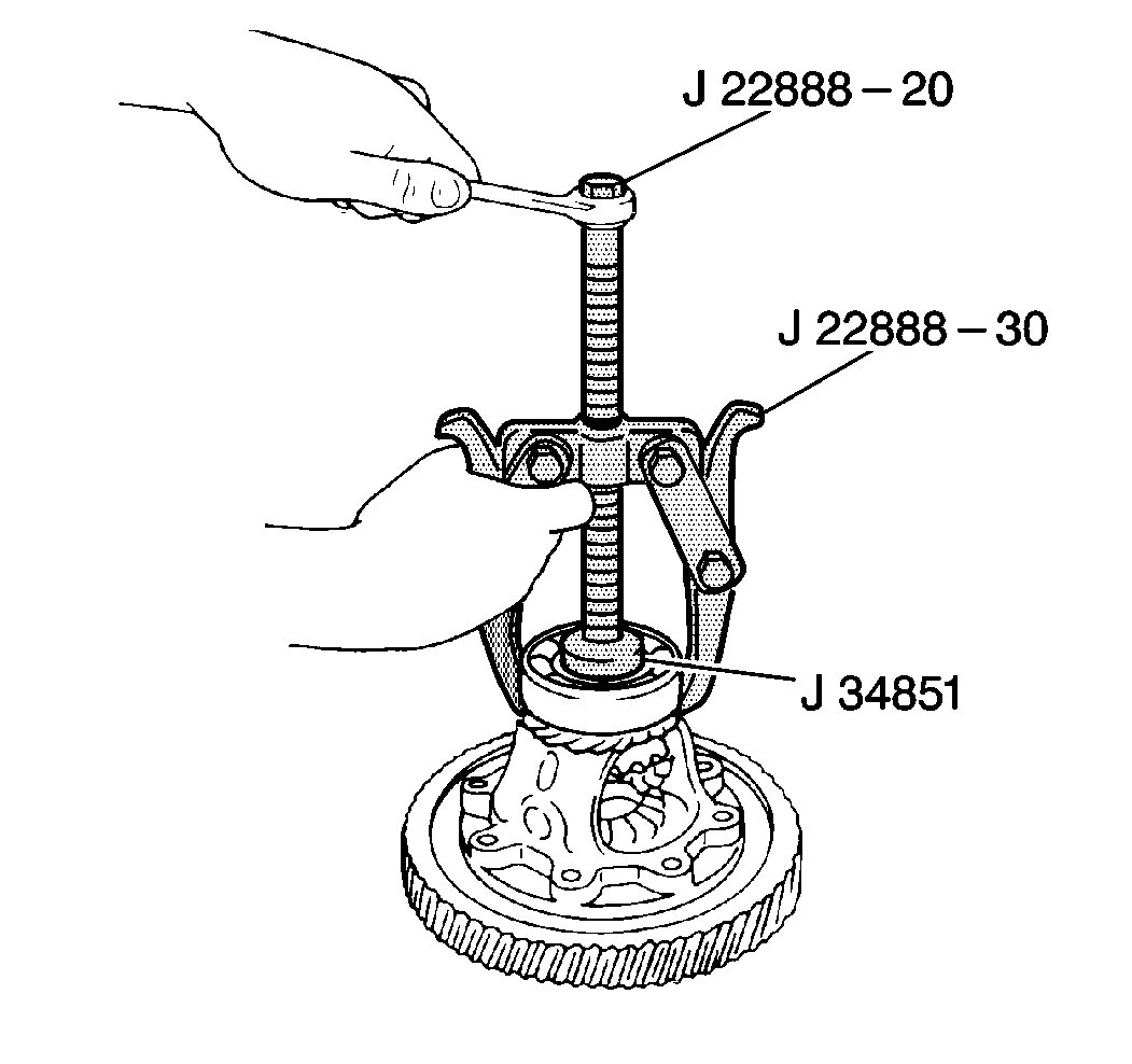
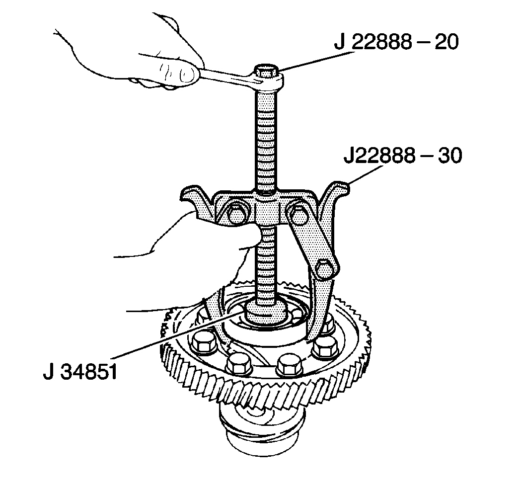
| • | J 22888-20A Universal Puller |
| • | J 22888-30 Puller Legs |
| • | J 34851 Differential Side Bearing Puller Plug |
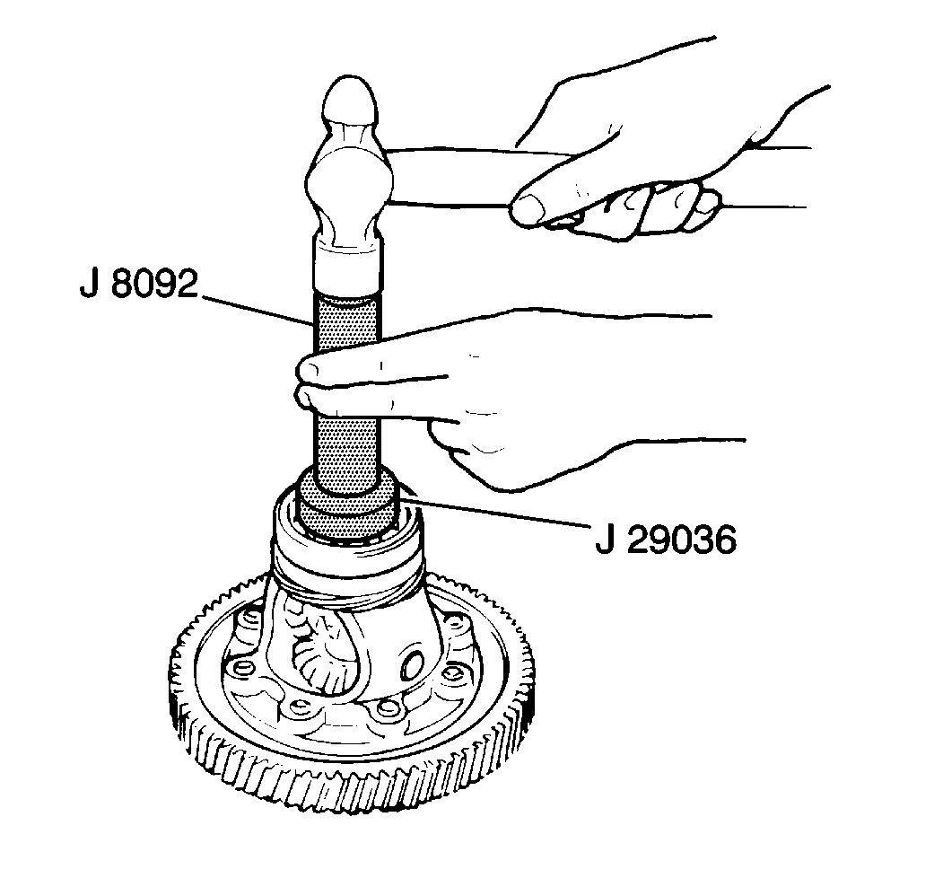
| • | J 29036 Differential Side Bearing Installer |
| • | J 8092 Driver Handle |
| • | J 8001 Dial Indicator Set |
Removal Procedure
- Use a J 22888-20A with two J 22888-30 and a J 34851 for support in order to remove the right differential side bearing from the differential carrier.
- Remove the speedometer drive gear from the differential carrier.
- Use the J 22888-20A with the J 22888-30 and the J 34851 for support in order to remove the left differential side bearing from the differential carrier.
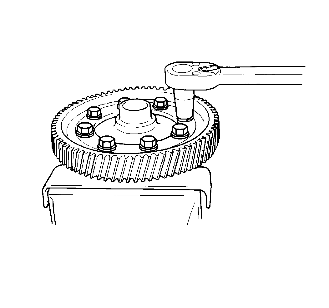
- Remove the eight ring gear bolts and the ring gear from the differential carrier.
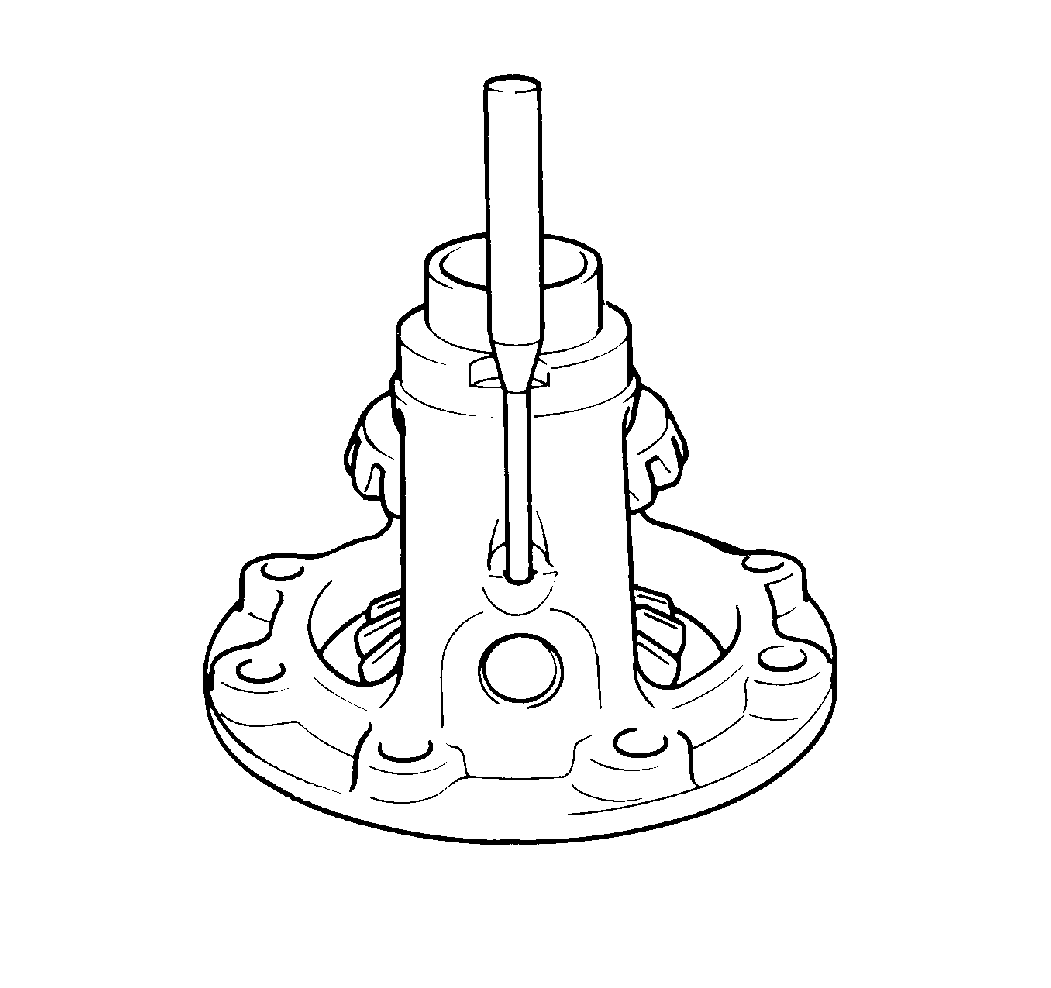
- Use a standard drift punch and a hammer in order to remove the pinion shaft roll pin from the differential carrier.
- Remove the following components from the differential carrier:
- Clean all the components thoroughly with clean solvent. Dry the components.
- Inspect all of the gears for the following conditions. Replace as necessary:
- Inspect the differential side bearing surfaces. Replace as necessary:
- Inspect the differential case gear and bearing surfaces for cracks and blue discoloration. These conditions indicate overheating or other damage. Replace as necessary.
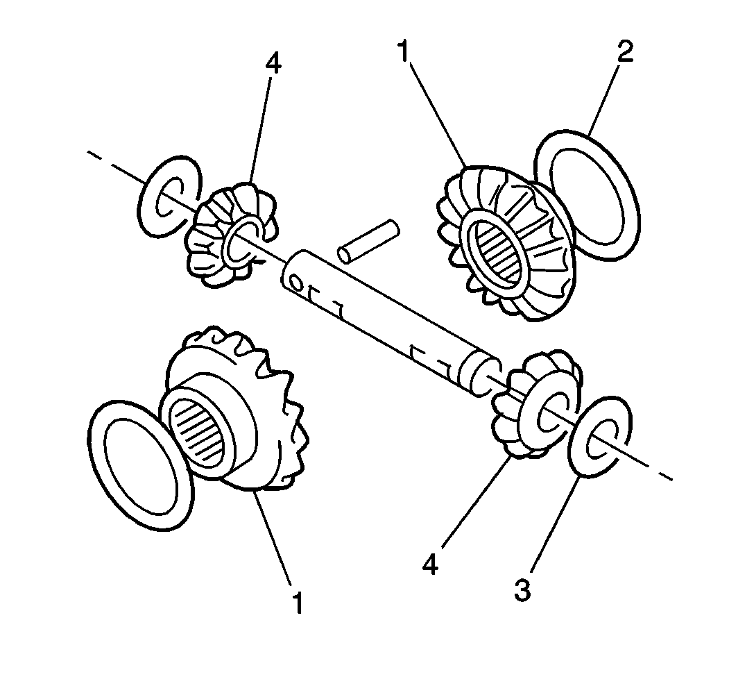
| 6.1. | The pinion shaft |
| 6.2. | The pinion gears (4) |
| 6.3. | The pinion washers (3) |
| 6.4. | The differential side gears (1) |
| 6.5. | The side gear selective shims (2) |
| • | Cracks |
| • | Chipped teeth |
| • | Broken teeth |
| • | Other damage |
| • | Roughness |
| • | Excessive wear |
Installation Procedure
- Install the following components into the differential carrier:
- Use a J 8001 in order to measure the left differential side gear end play.
- Use a J 8001 in order to measure the right differential side gear end play.
- Use a standard drift punch and hammer in order to install the pinion shaft roll pin into the differential carrier and the pinion shaft.
- Apply Loctite® 414 GM P/N 12345493 or equivalent to the threaded portion of all the eight ring gear bolts.
- Install the ring gear onto the differential carrier.
- Use a J 29036 , a J 8092 , and a J 34851 for support in order to install the left differential side bearing onto the differential carrier.
- Install the speedometer drive gear onto the differential carrier.
- Use the J 29036 with the J 8092 and the J 34851 for support in order to install the right differential side bearing onto the differential carrier.
| 1.1. | The side gear selective shims |
| 1.2. | The differential side gears |
| 1.3. | The pinion gear washers |
| 1.4. | The pinion gears |
| 1.5. | The pinion shaft |
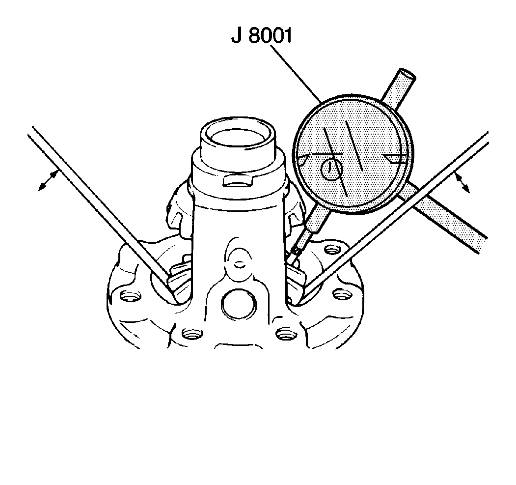
| 2.1. | Place the J 8001 plunger between the teeth of the left side gear . |
| 2.2. | Use two screwdrivers in order to move the left side gear up and down while observing the J 8001 . |
| 2.3. | The standard left differential side gear end play should be between 0.05 to 0.33 mm (0.002 to 0.013 in). |
| 2.4. | If the left differential side gear end play is below 0.05 mm (0.002 in), replace the left side gear selective shim with the appropriate selective shim in order to obtain the proper left differential side gear end play. Refer to Transmission Specifications . |
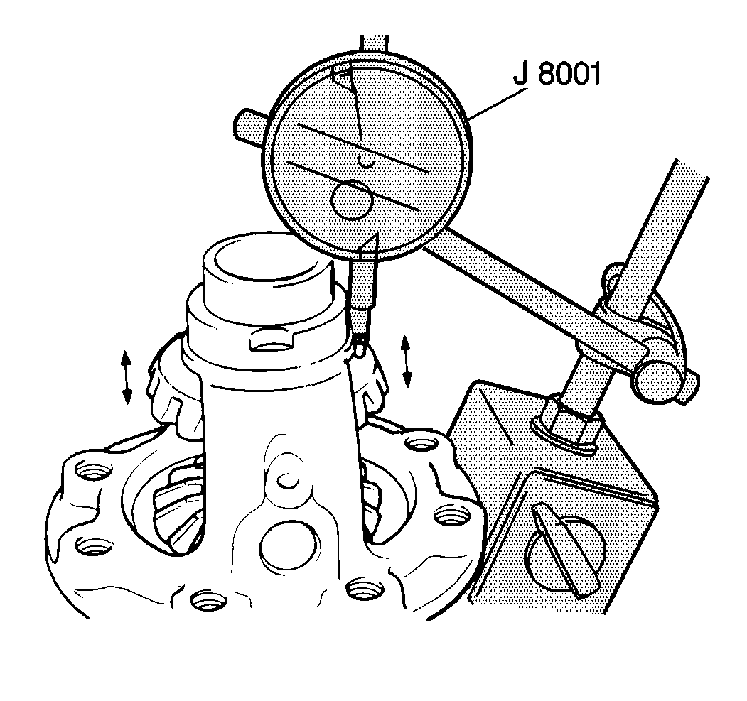
| 3.1. | Place the J 8001 plunger on the rear of the right differential side gear. |
| 3.2. | Use the fingertips of both hands in order to gently move the right differential side gear up and down while observing the J 8001 . |
| 3.3. | The standard right differential side gear end play should be between 0.05 to 0.33 mm (0.002 to 0.013 in). |
| 3.4. | If the right differential side gear end play is below 0.05 mm (0.002 in), replace the right side gear selective shims to obtain proper right differential side gear end play. Refer to Transmission Specifications . |
The roll pin should be flush with the differential carrier.
Notice: Use the correct fastener in the correct location. Replacement fasteners must be the correct part number for that application. Fasteners requiring replacement or fasteners requiring the use of thread locking compound or sealant are identified in the service procedure. Do not use paints, lubricants, or corrosion inhibitors on fasteners or fastener joint surfaces unless specified. These coatings affect fastener torque and joint clamping force and may damage the fastener. Use the correct tightening sequence and specifications when installing fasteners in order to avoid damage to parts and systems.
Secure the ring gear with the eight differential ring gear bolts.
Tighten
Tighten the differential ring gear bolts to 85 N·m (63 lb ft).
