GM Service Manual Online
For 1990-2009 cars only

Removal Procedure

  1. Raise and support the vehicle. Refer to Lifting and Jacking the Vehicle in General Information.
  2. Remove the rear tire and wheel assembly. Refer to Tire and Wheel Removal and Installation in Tires and Wheels.

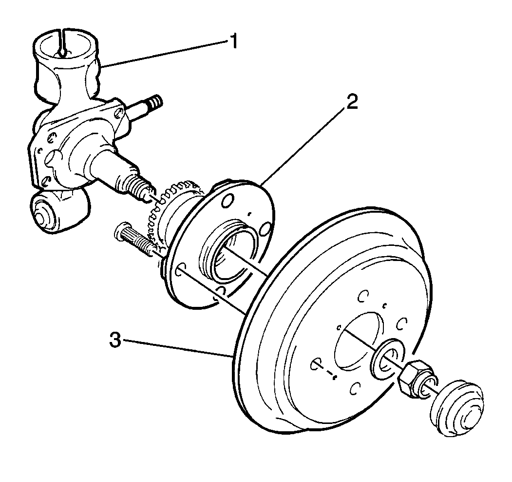
  3. Object Number: 177572  Size: SH
  4. On wheel hub equipped vehicles, remove the two recessed screws and the brake drum (3) from the wheel hub (2).
  5. Remove the spindle nut dust cap. Use a flat-bladed tool in order to pry off the cap.
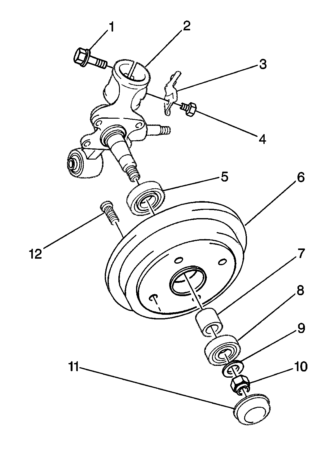
  6. Notice: If bearings are found to be defective on vehicles equipped with a wheel hub, replace the wheel hub and bearings as an assembly. The wheel hub and bearing are not serviceable.


    Object Number: 177571  Size: MH
  7. Unstake and remove the spindle nut (10) and the washer (9). On non wheel hub equipped vehicles, tap gently on the brake drum/hub assembly (6) with a hammer in order to break loose and remove the brake drum/hub assembly from the spindle.

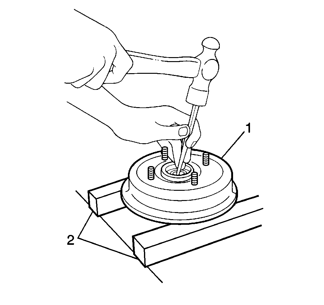
  8. Object Number: 177586  Size: SH
  9. Place the brake drum/hub assembly (1) on wood blocks (2) on a clean work bench.
  10. Use the following procedure in order to remove the inner bearing.
  11. • Drive out the inner bearing from the outboard side of the brake drum/hub assembly using a hammer and a punch.
    • Move the bearing spacer from side to side in order to facilitate placement of the punch. Move the bearing spacer in order to work the punch around the perimeter of the inner bearing.
  12. Remove the bearing spacer.

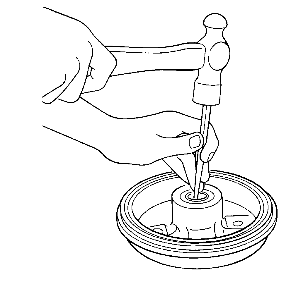
  13. Object Number: 177587  Size: SH
  14. Use the following procedure in order to remove the outer bearing.
  15. • Drive out the outer bearing from the inboard side of the brake drum/hub assembly using a hammer and a punch.
    • Work the punch around the perimeter of the outer bearing.
  16. Inspect both bearings for the following conditions. Replace the bearings if necessary.
  17. • Wear
    • Corrosion
    • Contamination by dirt or water

Installation Procedure

Tools Required

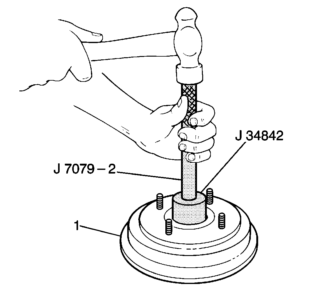
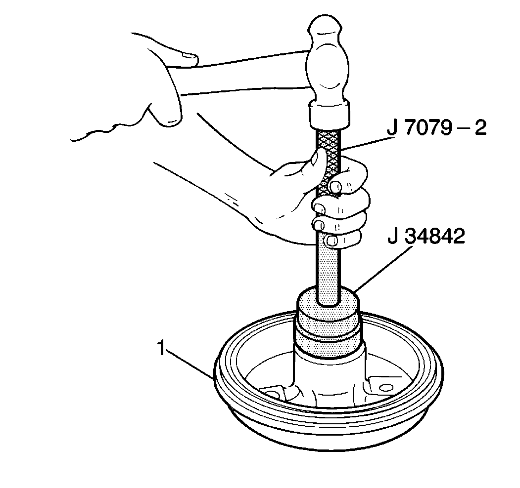
    • J 34842 Rear Wheel Bearing Installer
    • J 7079-2 Driver Handle

    Object Number: 177588  Size: SH

    Important: The outer and inner bearings differ in size. The outer cartridge is smaller in diameter than the inner cartridge. Both bearing cartridges are installed using the J 34842 . The two sides of the tool correspond to each bearing cartridge size.

  1. Install the outer bearing to the outboard side of the brake drum/hub assembly (1) using the J 34842 and the J 7079-2 .
  2. Important: The assembly will not fit on the knuckle spindle if the spacer lip faces toward the inner bearing.

  3. Install the bearing spacer to the brake drum/hub assembly. Ensure that the inner lip faces toward the outer bearing.
  4. Object Number: 177589  Size: SH
  5. Install the inner bearing to the inboard side of the brake drum/hub assembly (1) using the J 34842 and the J 7079-2 .
  6. On non ABS equipped vehicles, install the brake drum/hub assembly to the knuckle spindle.
  7. On ABS equipped vehicles, install the wheel hub to the knuckle spindle.

    Notice: Use the correct fastener in the correct location. Replacement fasteners must be the correct part number for that application. Fasteners requiring replacement or fasteners requiring the use of thread locking compound or sealant are identified in the service procedure. Do not use paints, lubricants, or corrosion inhibitors on fasteners or fastener joint surfaces unless specified. These coatings affect fastener torque and joint clamping force and may damage the fastener. Use the correct tightening sequence and specifications when installing fasteners in order to avoid damage to parts and systems.

  8. Install the washer and the spindle nut to the knuckle spindle.
  9. Tighten

        • On wheel hub equipped vehicles, tighten the spindle nut to 170 N·m (120 lb ft).
        • On non wheel hub equipped vehicles, tighten the spindle nut to 100 N·m (74 lb ft).
  10. Stake the spindle nut.
  11. Install the spindle nut dust cap.
  12. On wheel hub equipped vehicles, install the brake drum to the wheel hub. Secure the brake drum with the two recessed screws.

  13. Install the rear tire and wheel assembly. Refer to Tire and Wheel Removal and Installation in Tires and Wheels.
  14. Lower the vehicle.