For 1990-2009 cars only
Removal Procedure
- Disconnect the negative battery cable.
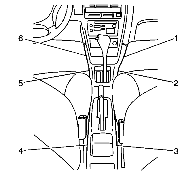
- Remove the 6 screws from the console (1,2,3,4,5,6).
- Remove the center console from the vehicle.
- Remove the rear console from the vehicle.
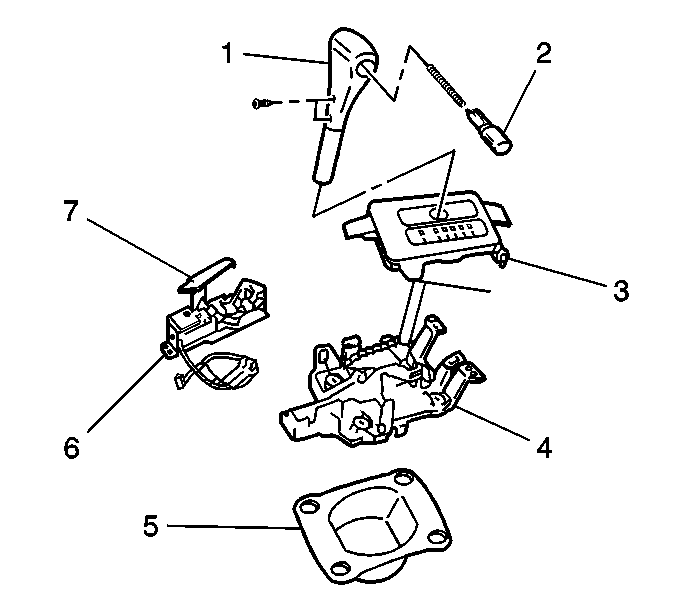
- Remove the 2 screws and the selector knob (1) from the selector lever.
- Unsnap the indicator cover from the selector lever.
- Remove the interlock cable end from the key release plate on the manual selector.
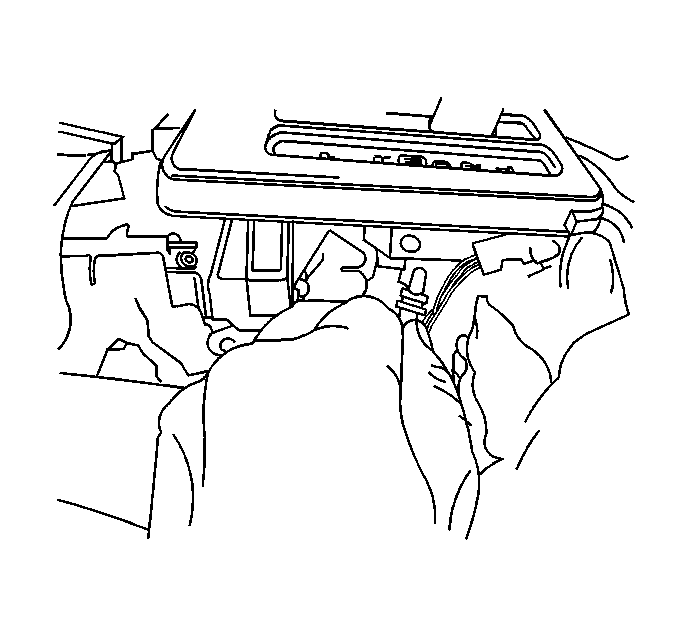
- Remove the illumination lamp bulb socket from the manual selector cover.
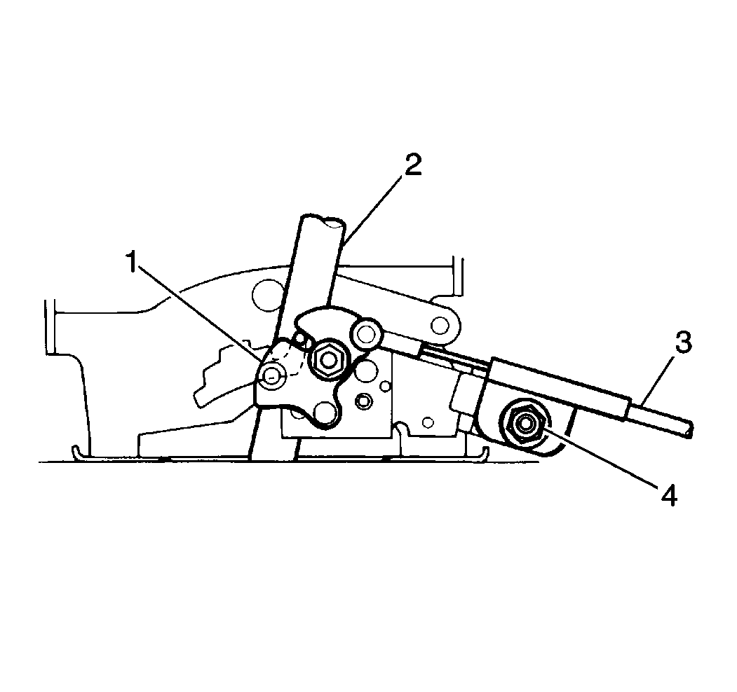
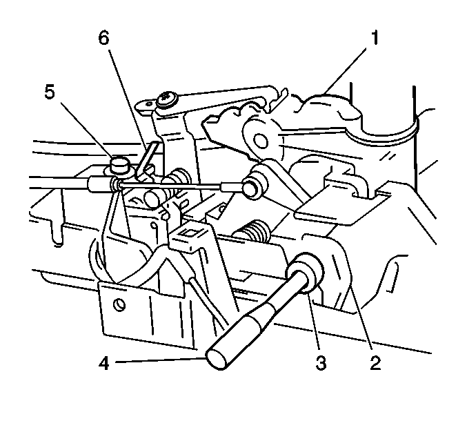
- Remove the interlock cable bolt (4).
- Remove the interlock cable (3) from the housing bracket of the selector lever (2).
- Remove the front carpet retainers, and pull back the front carpet.
- Remove the 5 screws, the upper steering column cover, and the lower steering column cover.
- Remove the lower steering column. Refer to Steering Column Replacement in Steering Wheel and Column.
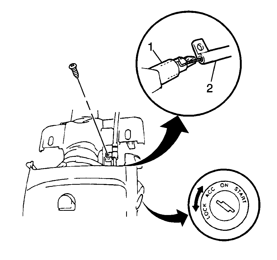
- Remove the screw and the clamp that retains the interlock cable (2) from the ignition switch.
- Push the release shaft (1) in at the ignition switch lock mechanism.
- Remove the cable end from the ignition switch, and the interlock cable assembly from the vehicle.
Caution: Unless directed otherwise, the ignition and start switch must be in the OFF or LOCK position, and all electrical loads must be OFF before servicing any electrical component. Disconnect the negative battery cable to prevent an electrical spark should a tool or equipment come in contact with an exposed electrical terminal. Failure to follow these precautions may result in personal injury and/or damage to the vehicle or its components.
Installation Procedure
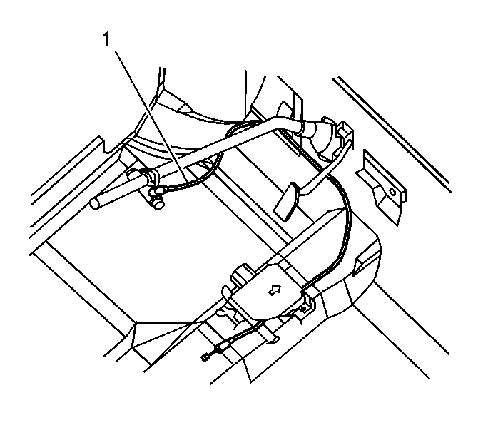
- Install the interlock cable (1). Route the cable to the ignition switch.
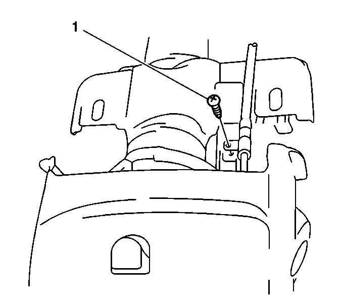
- With the ignition key in the ACC position, connect the cable to the steering lock and tighten the screw.
- Install the upper steering column cover and the lower steering column cover. Secure the covers with the 5 screws.
- Fit and position the front carpet. Secure the carpet with front carpet retainers.
- With the lock cover manually moved forward, shift the shift selector to the N position.
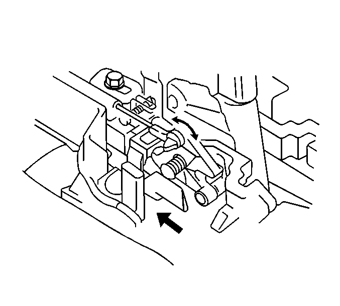
- Fix the key release cam by inserting the lock pin (4) into the holes of the cam and the solenoid bracket.
- Connect the cable end to the release cam.
- With the cable bracket pushed in the arrow direction by spring force.
- Tighten the cable bracket bolt.
- Install the manual selector cover.
- Install the manual selector cover illumination lamp bulb to the cover.
- Install the selector lever knob to the selector lever.
- Install the 2 screws.
- Remove the lock pin and turn the ignition switch to the ACC position.
- Place the selector lever to the P position and the lock plate of the shift lock solenoid manually moved forward, check that the key release cam moves smoothly by operating the know button of the selector lever.
- With the selector in the set P position, turn the key to the ACC position and then check for the following conditions.
- Adjust the cable.
- Install the rear console into the vehicle.
- Install the center into the vehicle.
- Install the 6 screws into the console (1,2,3,4,5,6).
- Connect the negative battery cable.
Tighten
Tighten the bolt to 13N·m (115 lb in).
| 16.1. | With the knob button released, the ignition key can be turned from ACC position to the LOCK position. |
| 16.2. | With the knob button pressed, the ignition key cannot be turned from the ACC position to the LOCK position. |

